
Inner heat dissipation device of spectrometer

A heat dissipation device and spectrometer technology, applied in the direction of measuring devices, instruments, spectrometry/spectrophotometry/monochromator, etc., can solve the problems of complex internal structure and high cost of cooling fans, and achieve heat dissipation effect, transfer The effect of stable and reliable wheel structure and simple structure

Inactive Publication Date: 2017-06-27
WUXI JINYIBO INSTR TECH CO LTD
View PDF7 Cites 0 Cited by
  • Summary
  • Abstract
  • Description
  • Claims
  • Application Information

AI Technical Summary

Problems solved by technology

[0002] The direct-reading spectrometer is a device that measures the intensity of different wavelength positions of the spectral line with a photodetector such as a photomultiplier tube. The electromagnetic radiation of the radiation source is separated into the required wavelength or wavelength region by a dispersive element, and at the selected wavelength (or scanning A certain band) for intensity measurement, due to the large number of internal electronic devices and relatively dense distribution, more heat will be generated when working for a long time, if the heat is not dissipated, it will affect the normal operation of the instrument, and the existing heat dissipation methods are generally The use of cooling fans can achieve a better cooling effect, but the electronic devices in the direct reading spectrometer are arranged in a flat and long rectangular area. In order to ensure the cooling effect, a row of cooling fans that are highly compatible with the rectangular area need to be arranged so The internal structure becomes complicated, and the working cost of multiple cooling fans is relatively high

Method used


Image

  • Inner heat dissipation device of spectrometer
  • Inner heat dissipation device of spectrometer
  • Inner heat dissipation device of spectrometer

Examples


Embodiment Construction

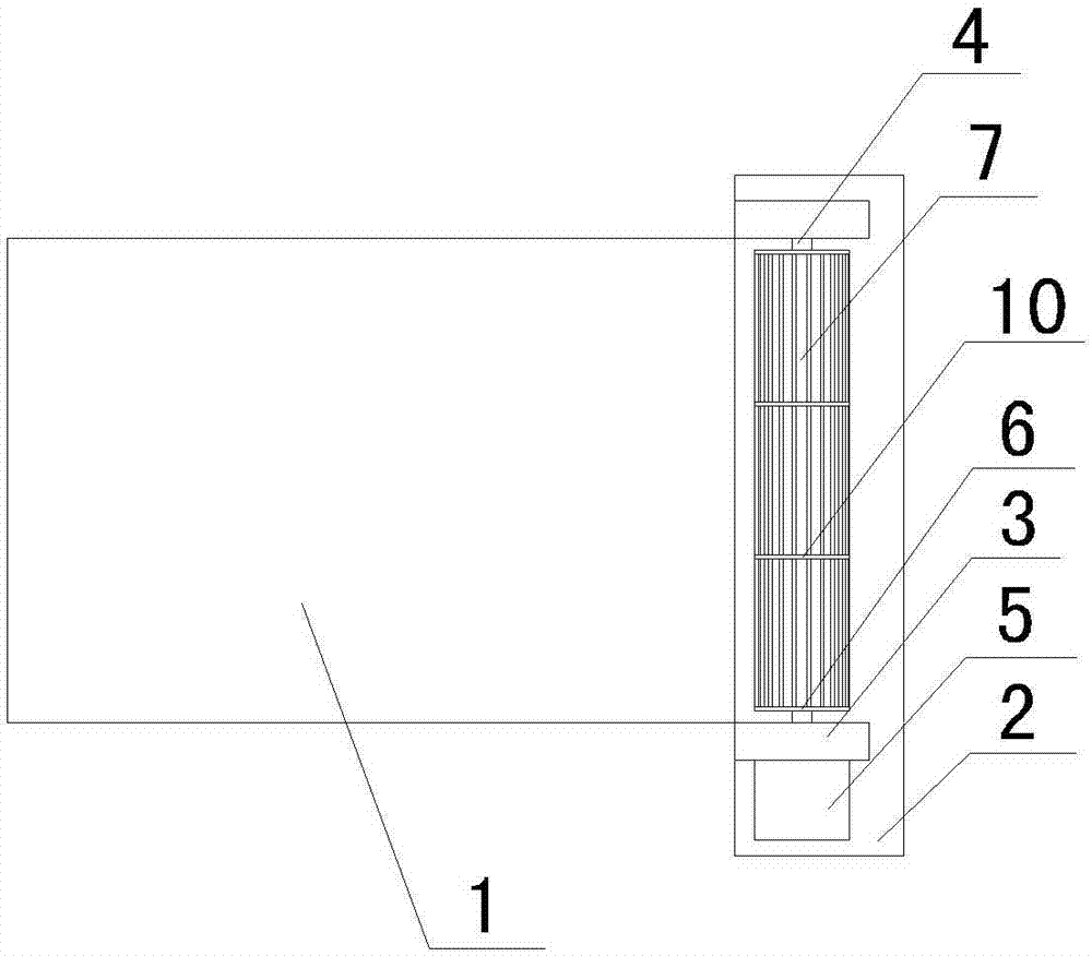
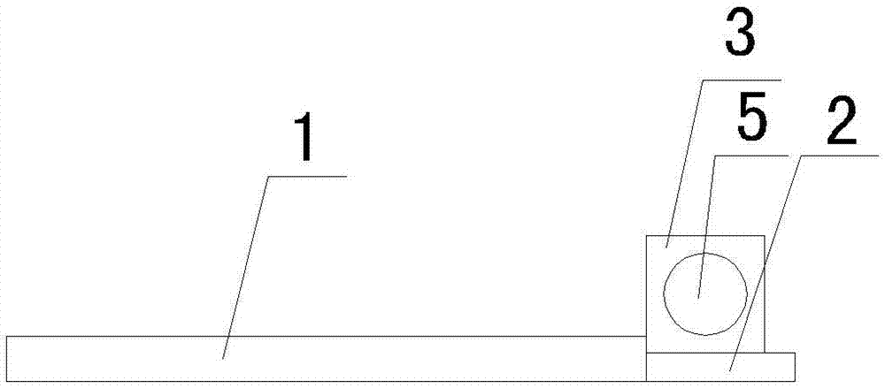
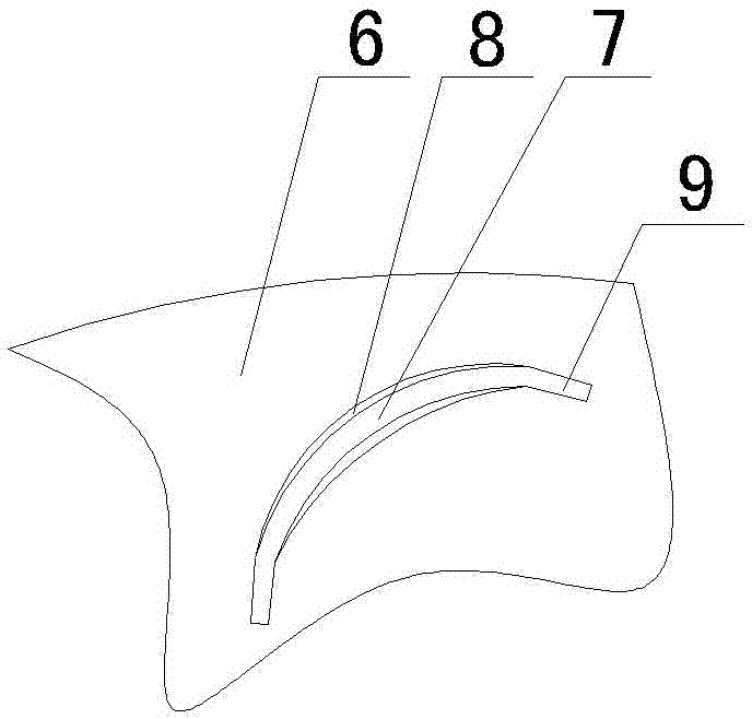
[0012] See figure 1 , figure 2 , image 3 As shown, a heat dissipation device in a spectrometer includes an electronic device mounting plate 1, a heat dissipation base 2 is installed on one side of the electronic device mounting plate 1, support bases 3 are installed at both ends of the heat dissipation base 2, and two support bases 3 pass through The rotating shaft 4 is equipped with a running wheel device, and one end of the rotating shaft 4 is connected to the drive motor 5. The rotating wheel device includes a disc 6 on both sides and a plurality of strip blades 7 installed on the disc 6, and the strip blades 7 are along the circumferential direction of the disc. Evenly arranged, the cross section of the strip blade 7 is arc-shaped, the central angle of the cross section of the strip blade is 90° to 120°, and the length of the strip blade 7 corresponds to the size of the electronic device mounting board 1, ensuring that the entire electronic device mounting board 1 is un...


PUM


Abstract

The invention relates to the field of inner heat dissipation of a spectrometer, in particular to an inner heat dissipation device of a spectrometer. The inner heat dissipation device is capable of conveniently achieving a heat dissipation effect, simple in structure and low in cost, comprises an electronic device installation plate and is characterized in that a heat dissipation base is installed on one side of the electronic device installation plate; support seats are installed on two ends of the heat dissipation base; rotating wheel devices are arranged on the two support seats through a rotation shaft; one end of the rotation shaft is connected with a driving motor; each rotating wheel device comprises discs on two sides and multiple long strip-shaped blades installed on the discs; the long strip-shaped blades are uniformly distributed along the circumferential directions of the discs; the cross section of each long strip-shaped blade is arc-shaped; and the length of each long strip-shaped blade corresponds to the size of the electronic device installation plate.

Description

technical field [0001] The invention relates to the technical field of heat dissipation inside a spectrometer, in particular to a heat dissipation device inside a spectrometer. Background technique [0002] The direct-reading spectrometer is a device that measures the intensity of different wavelength positions of the spectral line with a photodetector such as a photomultiplier tube. The electromagnetic radiation of the radiation source is separated into the required wavelength or wavelength region by a dispersive element, and at the selected wavelength (or scanning A certain band) for intensity measurement, due to the large number of internal electronic devices and relatively dense distribution, more heat will be generated when working for a long time, if the heat is not dissipated, it will affect the normal operation of the instrument, and the existing heat dissipation methods are generally The use of cooling fans can achieve a better cooling effect, but the electronic dev...

Claims


Application Information

Patent Timeline
Patent Type & Authority Applications(China)
IPC IPC(8): G01J3/02
CPCG01J3/02
Inventor 叶反修史先春沈永祥沈永胜叶春晖
Owner WUXI JINYIBO INSTR TECH CO LTD
Learn More