Antenna matching debugging method and terminal thereof

An antenna matching and terminal technology, which is applied to measuring devices, instruments, transmitter monitoring, etc., can solve the problems of time-consuming, cumbersome operation, and low efficiency, and achieve the effect of high debugging efficiency and simple operation

Inactive Publication Date: 2017-06-27
GUIZHOU FORTUNESHIP TECH CO LTD
View PDF4 Cites 4 Cited by
  • Summary
  • Abstract
  • Description
  • Claims
  • Application Information

AI Technical Summary

Problems solved by technology

[0004] The present invention provides a method for antenna matching debugging and its terminal to solve the technical problems of cumbers

Method used


Image

  • Antenna matching debugging method and terminal thereof
  • Antenna matching debugging method and terminal thereof
  • Antenna matching debugging method and terminal thereof

Examples


Embodiment Construction

[0073] Example embodiments will now be described more fully with reference to the accompanying drawings. Example embodiments may, however, be embodied in many forms and should not be construed as limited to the embodiments set forth herein. Rather, these embodiments are provided so that this disclosure will be thorough and complete, and will fully convey the concept of the example embodiments to those skilled in the art. For convenience or clarity, the thickness and size of each layer shown in the drawings and the number of related elements may be exaggerated, omitted, or schematically shown. In addition, the size of elements does not entirely reflect an actual size, and the number of related elements does not entirely reflect an actual number. The same reference numbers in the figures indicate the same or similar structures.

[0074] Furthermore, the described features and structures may be combined in any suitable manner in one or more embodiments. In the following descri...


PUM


Abstract

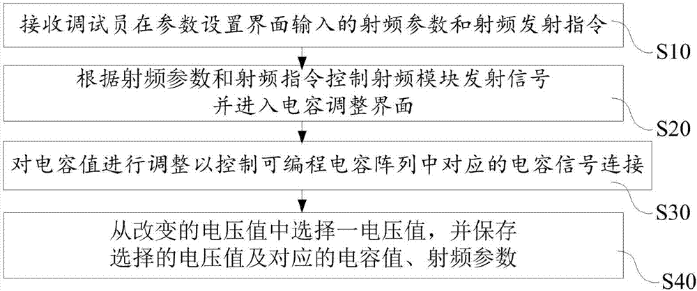
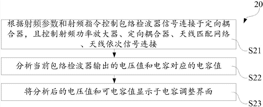
The invention discloses an antenna matching debugging method and terminal thereof. The antenna matching debugging method comprises the following steps: receiving a radio frequency parameter and a radio frequency emission instruction input in a parameter setting interface by a debugging personnel; controlling a radio frequency module to emit a signal according to the radio frequency emission instruction, and entering a capacitance adjusting interface, wherein the adjusting interface comprises a voltage value and an adjustable capacitance value; adjusting the capacitance value so as to conduct the capacitance in the programmable capacitance array, thereby enabling a voltage value to be changed along the adjusting of the capacitance value; selecting a voltage value according to the changed voltage value, and saving the saved voltage value, the corresponding capacitance value and the radio frequency parameter. By use of the above method disclosed by the invention, the semi-automatic or automatic debugging of the antenna matching debugging can be realized, the operation is simple, convenient and high in debugging efficiency. Correspondingly, the terminal capable of debugging the antenna has the above mentioned effect as well.

Description

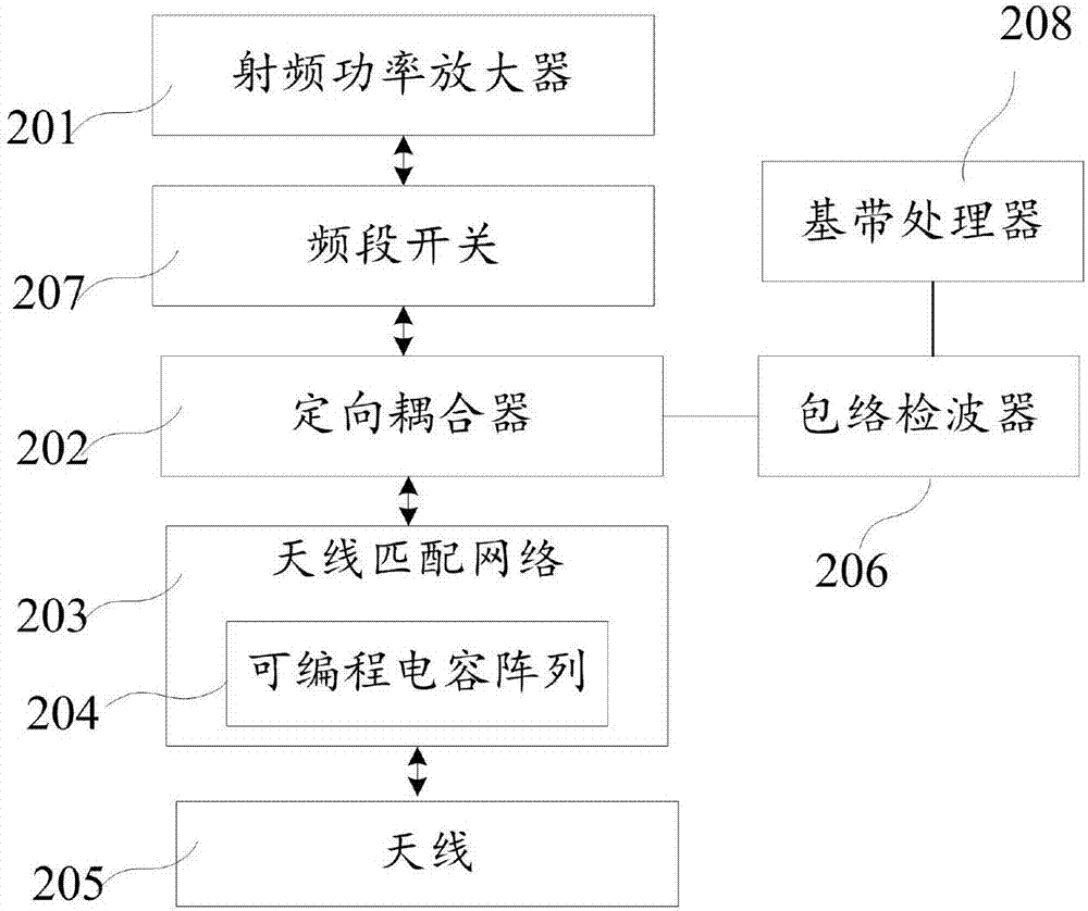
technical field [0001] The invention relates to the technical field of electronic equipment, in particular to a method for antenna matching debugging and a terminal thereof. Background technique [0002] At present, there are more and more frequency bands for wireless communication terminals, and the resulting problem is that the antenna space is becoming more and more tight, and the antenna design and matching are becoming more and more difficult. How to cover more frequency bands in a limited antenna space and make each frequency band match as much as possible becomes very important. [0003] In the prior art, the radio frequency module of the wireless communication terminal includes a plurality of radio frequency power transmitters and a plurality of frequency band switching switches, an antenna matching network, and an antenna which are sequentially connected by signals, and the frequency band switching can be switched through the frequency band switching switches. The ...

Claims


Application Information

Patent Timeline
IPC IPC(8): H04B17/12H04B17/21H04B17/15H04B17/29G01R19/30
CPCG01R19/30H04B17/12H04B17/15H04B17/21H04B17/29
Inventor 张立新周毕兴
Owner GUIZHOU FORTUNESHIP TECH CO LTD
Why Eureka
Try Eureka