Automatic recognizing cutting mechanism

A cutting mechanism and automatic identification technology, applied in welding equipment, laser welding equipment, metal processing equipment, etc., can solve the high requirements of workers' operation skills and fatigue resistance, the inability to use batch cutting, and the low efficiency of manual scissors, etc. problems, to achieve fast and accurate automatic cutting, improve cutting efficiency, and improve cutting quality

Active Publication Date: 2017-06-30
GUANGDONG ESQUEL TEXTILES CO LTD
View PDF9 Cites 11 Cited by
  • Summary
  • Abstract
  • Description
  • Claims
  • Application Information

AI Technical Summary

Problems solved by technology

But when cutting knitted striped cloth, since the striped cloth is flattened, the shape of the stripes is naturally slightly curved, but most of the ready-to-wear styles have strict requirements on the position and shape of the stripes, so when cutting a certain position (such as shirt foot, cuff, etc.), in order to ensure that the stripes are at the specified size position of the clothes, and keep the stripes equidistant and evenly parallel to the cutting edge, the cutter needs to follow the stripe position size requirements and The curving curves of the stripes are manually trimmed one by one with scissors, and cannot be cut in batches with faster tools such as electric scissors
Manual scissors are not only inefficient and the quality of the cuts is not high, but also because workers need to stare at the stripes of the fabric for a long time and use scissors to cut, the requirements for workers' operating skills and fatigue resistance are very high; A certain amount of fabric needs to be wasted on the piece for the reserved space for measuring the size of the stripes when trimming with scissors
No matter in terms of efficiency, quality or manpower and material resources, it is a great loss and waste

Method used


Image

  • Automatic recognizing cutting mechanism
  • Automatic recognizing cutting mechanism

Examples


Embodiment Construction

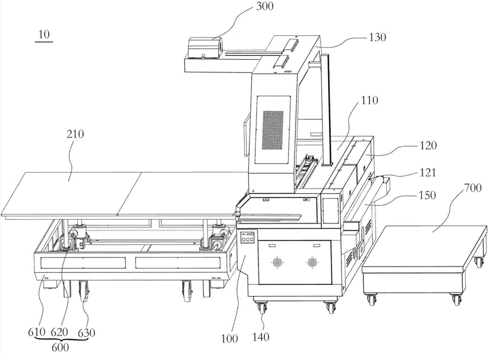
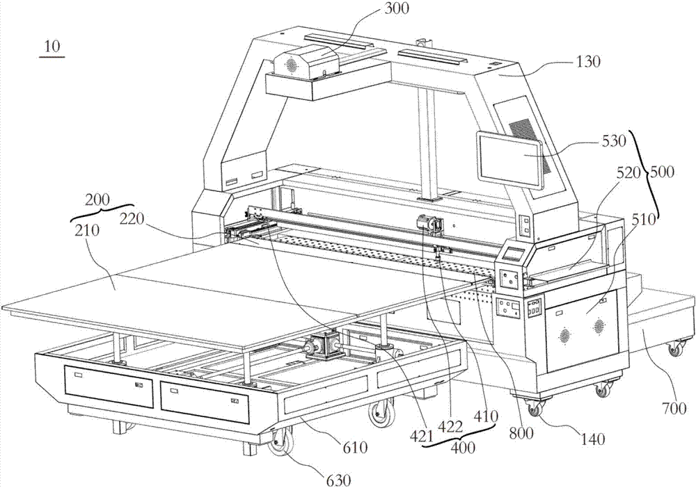
[0026] In order to facilitate the understanding of the present invention, the present invention will be described more fully below with reference to the associated drawings. Preferred embodiments of the invention are shown in the accompanying drawings. However, the present invention can be embodied in many different forms and is not limited to the embodiments described herein. On the contrary, these embodiments are provided to make the understanding of the disclosure of the present invention more thorough and comprehensive.

[0027] It should be noted that when an element is referred to as being “fixed” to another element, it can be directly on the other element or there can also be an intervening element. When an element is referred to as being "connected to" another element, it can be directly connected to the other element or intervening elements may also be present.

[0028] Unless otherwise defined, all technical and scientific terms used herein have the same meaning as...


PUM


Abstract

The invention discloses an automatic recognizing cutting mechanism. The automatic recognizing cutting mechanism comprises a machine table, a support part, an image acquiring part, a processing part and a cutting part. The machine table has a working platform; the support part has a support plate, a shielding plate and a shielding drive part; the shielding drive part is arranged on the machine table and connected to the shielding plate, the shielding plate is attached to the support plate in an initial state, after cloth is cut, the shielding plate is driven by the shielding drive part to be turned over so as to be drawn out from a position below the cloth and to press the end part of the cut cloth; the image acquiring part is arranged on the machine table to acquire an image of the cloth, the processing part is connected to the image acquiring part to determine the position of a cutting line on the cloth by the image of the cloth; and the cutting part is used for cutting the cloth along the position of the cutting line on the cloth. The automatic recognizing cutting mechanism can quickly and automatically recognize stripes and can automatically and precisely cut according to a radian curve of the stripe lines and is high in cutting efficiency.

Description

technical field [0001] The invention relates to the field of garment making, in particular to an automatic identification and cutting mechanism. Background technique [0002] In the existing garment fabric cutting process, the general cutting method is to fold the fabric into a pile, and then use electric scissors or use an automatic cutting machine to cut. But when cutting knitted striped cloth, since the striped cloth is flattened, the shape of the stripes is naturally slightly curved, but most of the ready-to-wear styles have strict requirements on the position and shape of the stripes, so when cutting a certain position (such as shirt foot, cuff, etc.), in order to ensure that the stripes are at the specified size position of the clothes, and keep the stripes equidistant and evenly parallel to the cutting edge, the cutter needs to follow the stripe position size requirements and The curved curves of the stripes are trimmed piece by piece by hand with scissors, and it is...

Claims


Application Information

Patent Timeline
Patent Type & Authority Applications(China)
IPC IPC(8): B23K26/38B23K26/40B23K26/70B23K26/16B23K26/03
CPCB23K26/032B23K26/16B23K26/38B23K26/402B23K26/702
Inventor 夏天宇熊显军王晓芸彭涛陈为华区子华何梁博陈继尊梁伟伦曾登峰苏文杰
Owner GUANGDONG ESQUEL TEXTILES CO LTD
Why Eureka
Try Eureka