Welding jig and automobile lamp manufacturing method

A welding jig and jig technology, applied in the jig field, can solve the problems of insufficient verticality of the shape, long heating and cooling time of the jig, etc., so as to speed up the heating and cooling process, ensure the welding quality, and ensure the straightness. Effect

Inactive Publication Date: 2017-06-30
GUANGZHOU GONGZHU SCI HLDG CO
View PDF5 Cites 5 Cited by
  • Summary
  • Abstract
  • Description
  • Claims
  • Application Information

AI Technical Summary

Problems solved by technology

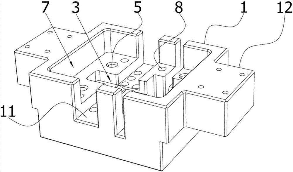
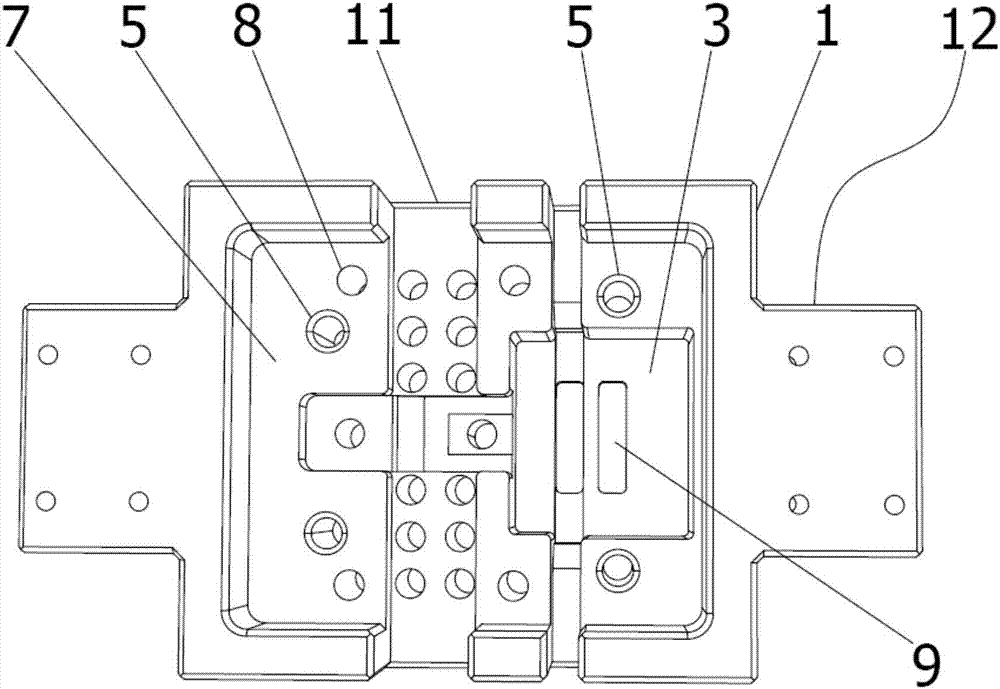
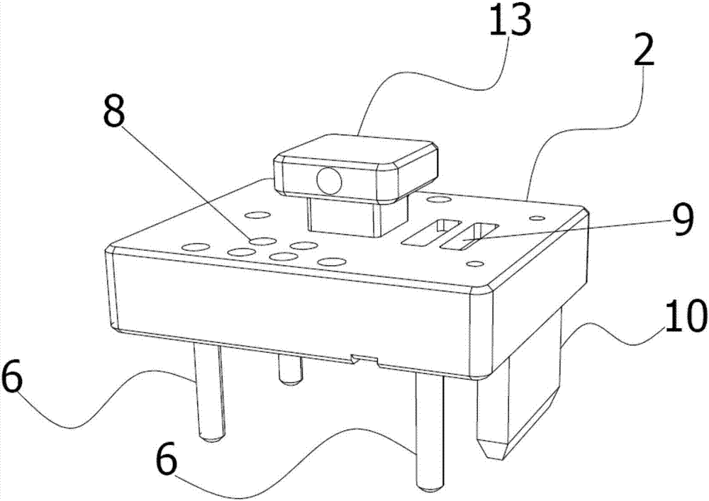
[0005] The object of the present invention is to provide a welding fixture and a method for manufacturing a car lamp to solve the problem of insufficient verticality of the shape of the welding fixture in the prior art in the welding and molding of other devices such as car lights, and the long heating and cooling time of the fixture The problem

Method used


Image

  • Welding jig and automobile lamp manufacturing method
  • Welding jig and automobile lamp manufacturing method
  • Welding jig and automobile lamp manufacturing method

Examples


Embodiment Construction

[0037] The technical solutions of the present invention will be clearly and completely described below in conjunction with the accompanying drawings. Apparently, the described embodiments are part of the embodiments of the present invention, but not all of them. Based on the embodiments of the present invention, all other embodiments obtained by persons of ordinary skill in the art without making creative efforts belong to the protection scope of the present invention.

[0038] In the description of the present invention, it should be noted that the terms "center", "upper", "lower", "left", "right", "vertical", "horizontal", "inner", "outer" etc. The indicated orientation or positional relationship is based on the orientation or positional relationship shown in the drawings, and is only for the convenience of describing the present invention and simplifying the description, rather than indicating or implying that the referred device or element must have a specific orientation, ...


PUM


Abstract

The invention provides a welding jig. The welding jig comprises an upper mold and a lower mold sequentially from top to bottom, a lower jig cavity is formed in the upper surface of the lower mold, the lower surface of the upper mold is provided with an upper jig cavity corresponding to the lower jig cavity, the lower mold is provided with a positioning hole located outside the lower jig cavity, the upper mold is provided with a positioning column corresponding to the positioning hole, a groove is formed in the upper surface of the lower mold, the lower jig cavity is arranged in the groove, and the upper mold can be arranged in the groove in an attaching manner; the upper mold and the lower mold are each provided with a through hole, and the through holes penetrate the groove, the lower jig cavity and the upper jig cavity; the welding jig is accurate in positioning, simple and practical, the groove, the positioning hole and the positioning column are used for ensuring perpendicularity of the welding component in the horizontal and vertical direction; through the through holes, the heating and cooling process of the jig is quickened. On this basis, the invention further provides a method for manufacturing an automobile lamp through the welding jig.

Description

technical field [0001] The invention relates to the technical field of jigs, in particular to a welding jig and a method for manufacturing a vehicle lamp. Background technique [0002] A jig is a tool used to assist in controlling position or motion (or both). Fixtures can be divided into process assembly fixtures, project test fixtures and circuit board test fixtures. Among them, the process assembly fixtures include assembly fixtures, welding fixtures, disassembly fixtures, glue dispensing fixtures, irradiation fixtures, adjustment fixtures and cutting fixtures. [0003] Among them, the welding fixture is a welding fixture designed and manufactured according to the size coordinate points of the shape of the welded part calibrated during the design of the welding product. [0004] The welding of components in the electronics industry requires that the corresponding components have high positioning accuracy. However, in the prior art, it is difficult to achieve precise po...

Claims


Application Information

Patent Timeline
Patent Type & Authority Applications(China)
IPC IPC(8): B23K37/04
CPCB23K37/0443
Inventor 贾涛涛
Owner GUANGZHOU GONGZHU SCI HLDG CO
Why Eureka
Try Eureka