
Positioning and clamping device for machining plate parts and using method of positioning and clamping device

A disc-type part, positioning and clamping technology, applied in positioning devices, metal processing equipment, metal processing mechanical parts, etc., can solve the problems of large processing removal, insufficient precision, and large difference in axial space position, and achieve improved processing. Quality and yield, avoid machining deformation, counteract the effect of circumferential cutting force

Inactive Publication Date: 2017-06-30
JIANGSU UNIV OF SCI & TECH
View PDF8 Cites 5 Cited by
  • Summary
  • Abstract
  • Description
  • Claims
  • Application Information

AI Technical Summary

Problems solved by technology

[0003] At present, the axial clamping mode of the central round hole is mostly used in the processing of thin-walled disc parts, which solves the positioning and fixing problems of the processed disc parts, but there are generally problems of deformation and insufficient precision caused by processing flexibility, especially the edge of suspended parts. , the lack of effective support to overcome the cutting force, especially the main cutting force along the circumferential direction cannot be offset, resulting in the processing deformation of disc thin-walled parts is difficult to solve
Taking the injector flange of a diesel engine as an example, the plate is large and thin, the process structure is complex, and the axial space position is greatly different, resulting in a large amount of machining removal, and obvious flexible deformation and machining in the process of milling the shape and milling guide rail surface. Due to the error, the one-time processing pass rate of the flange plate of the domestic marine diesel engine injector does not exceed 20%.

Method used


Image

  • Positioning and clamping device for machining plate parts and using method of positioning and clamping device
  • Positioning and clamping device for machining plate parts and using method of positioning and clamping device
  • Positioning and clamping device for machining plate parts and using method of positioning and clamping device

Examples


Embodiment 1

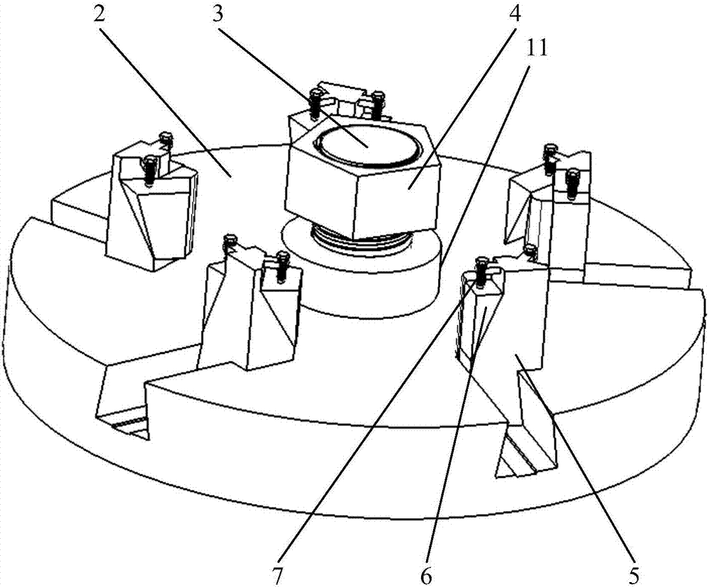
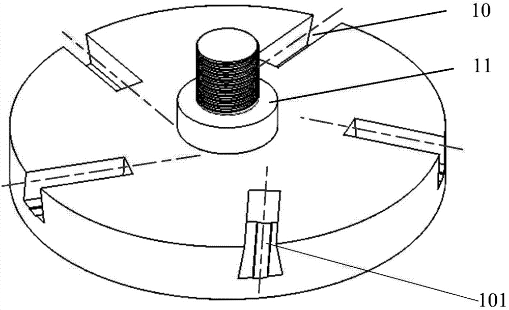
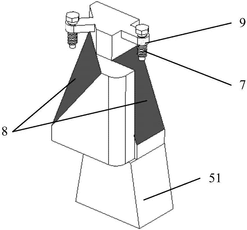
[0035] Such as Figure 5 As shown, what is to be processed in this implementation is a typical disc part diesel engine injector flange 1, which is generally in the shape of a disc with a large radial dimension and a small axial direction, with a circular inner hole in the center and a stepped end surface. Five characteristic structures and their corresponding positioning parts are symmetrically distributed in the center. The size and shape parameters of the positioning parts are the requirements of the fixed clamping device (especially the moving slider 5, the upper slide rail 10 of the fixture base 2 and the clamping pressure block 6). Design Basis. Flange 1 of injector of diesel engine has the characteristics of typical disk parts such as large disk and thin wall, complex structure, and large amount of cutting and processing. It is easy to process deformation in the two-pass milling process of its groove shape and slide rail 10 sides, which needs to be solved. The problem o...


PUM


Abstract

The invention discloses a positioning and clamping device for processing disc parts and a method for using the same. It comprises a clamp base and a moving slider. The center of the clamp base is provided with a positioning boss, and the radial direction of the clamp base is provided with several slide rails. , each slide rail is equipped with a matching moving slider, the bottom of the moving slider moves back and forth along the sliding rail, and the middle part of the moving slider is provided with two sliding block slopes, and the sliding block slopes are equipped with matching The top of the moving slider is provided with a threaded hole, and the threaded hole is provided with a compression bolt for controlling the clamping of the corresponding compression block. The invention can effectively offset the cutting force in the circumferential direction, avoid the processing deformation caused by insufficient rigidity of parts, and improve the processing quality and pass rate.

Description

technical field [0001] The invention relates to a fixture design technology, in particular to a positioning and clamping device suitable for processing thin-walled parts such as a diesel engine injector flange and a method for using the same. Background technique [0002] Disc parts are typical mechanical parts widely used, and they undertake functions such as support, connection and transmission in mechanical equipment. Disc parts are usually composed of features such as stepped end faces, central holes, outer circular contours, and central symmetry. It is easy to deform during the process. [0003] At present, the axial clamping mode of the central round hole is mostly used in the processing of thin-walled disc parts, which solves the positioning and fixing problems of the processed disc parts, but there are generally problems of deformation and insufficient precision caused by processing flexibility, especially the edge of suspended parts. , the lack of effective suppor...

Claims


Application Information

Patent Timeline
IPC IPC(8): B23Q3/06
CPCB23Q3/062
Inventor 田桂中刘晓飞周宏根郭巨寿王东军李磊李国超刘金峰景旭文
Owner JIANGSU UNIV OF SCI & TECH
Learn More