
Novel tunnel inclined shaft specific and special construction method

A construction method and inclined shaft technology, which is applied in tunnels, tunnel linings, shaft linings, etc., can solve the problems of surrounding rock settlement deformation, difficult deformation of surrounding rocks, voiding, etc., and achieve the effects of cost saving, rapid construction, and easy operation

Active Publication Date: 2017-06-30
THE 5TH ENG OF CHINA RAILWAY 22TH BUREAU GROUP +2
View PDF3 Cites 19 Cited by
  • Summary
  • Abstract
  • Description
  • Claims
  • Application Information

AI Technical Summary

Problems solved by technology

[0003] The first method is used in the application of long-span loess tunnels, because when the steel frame support of the extended inclined shaft section is removed by turning around, it is very easy to cause the surrounding rock to settle and deform, or even collapse, resulting in the failure of the inclined shaft to enter the main tunnel. Deformation is controlled
[0004] The second method, although adopting the concept of climbing the slope and raising the roof to build the shed hole, has relatively large disadvantages in the method of raising the vault height of the inclined shaft near the main tunnel and setting a reinforcing ring at the intersection. First, the height-span ratio of the inclined shaft is increased, and the requirements for the initial support structure are strict (the steel frame must be denser and the support measures must be strengthened). The second is that the stiffness and stability of the connection (or bottom) of the reinforcement ring at the intersection of the inclined shaft and the main tunnel and the lining structure of the inclined shaft are not enough, and the stress conditions are not uniform, which may lead to the cracking of the main tunnel support body

Method used


Image

  • Novel tunnel inclined shaft specific and special construction method
  • Novel tunnel inclined shaft specific and special construction method
  • Novel tunnel inclined shaft specific and special construction method

Examples


Embodiment Construction

[0039] In order to make the object, technical solution and advantages of the present invention more clear, the present invention will be further described in detail below in conjunction with the examples. It should be understood that the specific embodiments described here are only used to explain the present invention, not to limit the present invention.

[0040] The application principle of the present invention will be described in detail below in conjunction with the accompanying drawings.

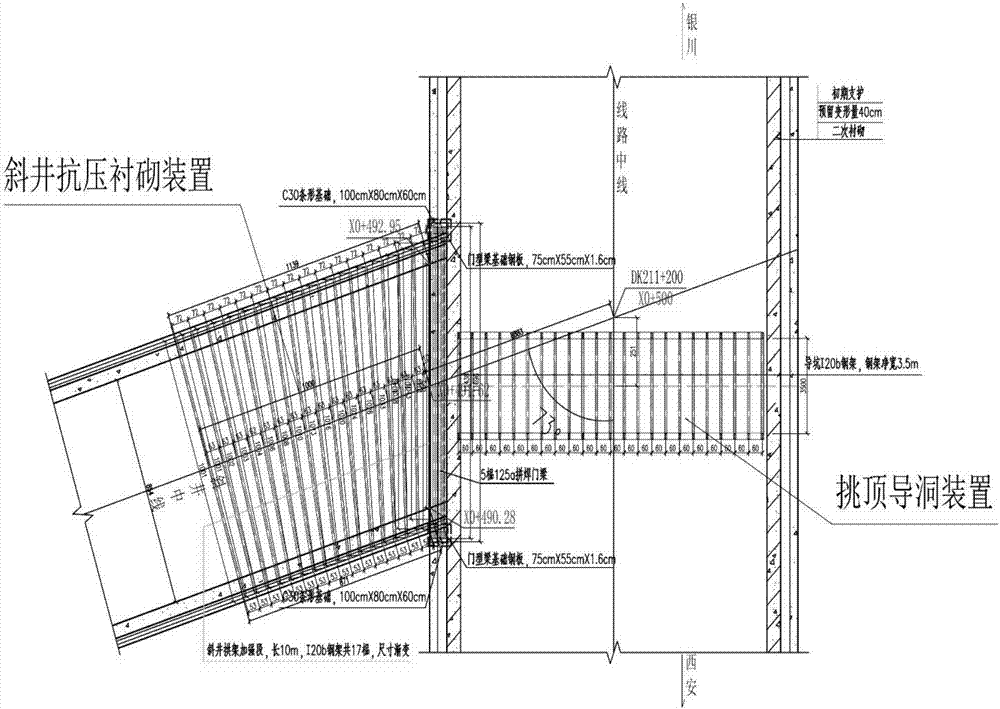
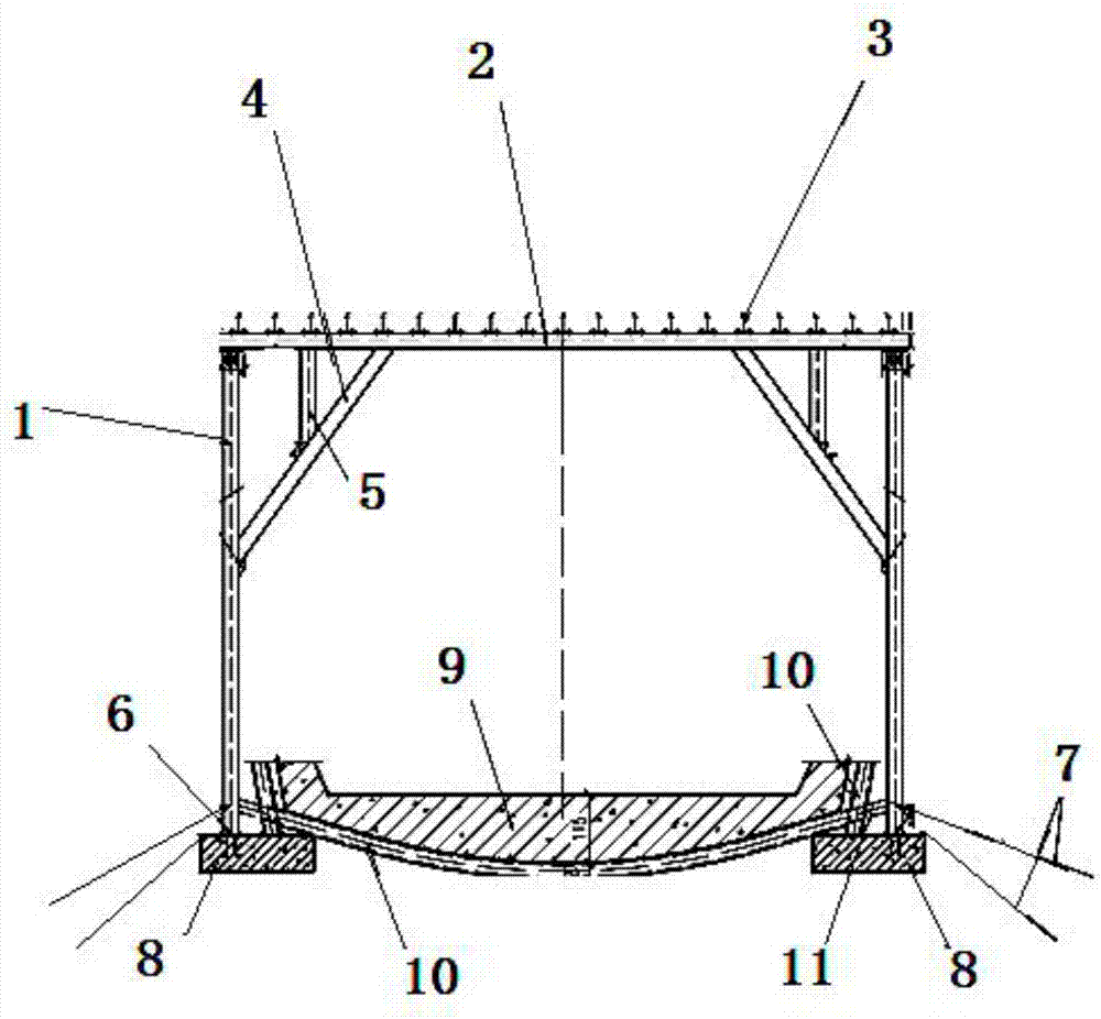
[0041] Such as figure 1 As shown, the new tunnel inclined shaft selection special construction method provided by the embodiment of the present invention includes the following steps:

[0042] S101: The plane intersection angle between the inclined shaft and the main tunnel is 92°. When the inclined shaft is close to the intersecting mileage with the main tunnel, a small pilot pit is used to enter the main tunnel body for excavation from the intersection mileage between the main tunn...


PUM


Abstract

The invention belongs to the technical field of tunnel construction, and discloses a novel tunnel inclined shaft specific and special construction method. A main tunnel section is decomposed into a small cavern in a cross entry mode, then sectional digging is conducted toward the two sides of the small cavern separately, with an auxiliary tunnel composite lining structure being a base point, a primary support structure in the small cavern is supported to form a stable triangular structure, and construction conversion of digging the main tunnel toward the two sides of the main tunnels through a step method is quickly completed; when an inclined shaft is close to a main tunnel cross mileage, from a cross interface, through a method of digging a small pilot tunnel, a main tunnel body is entered to be dug, a main tunnel primary support steel frame is erected in the pilot tunnel, an erection point is acted on the upper part of an inclined shaft five-truss spliced door beam, bolt connection is conducted, a stable system of early closed loop support is completed, then according to a three-step method, digging is conducted toward the two sides of the main tunnel to form a main tunnel standard fracture surface, and a main tunnel primary support thickness and a deformation sunk amount of 40cm need to be reserved during construction of the pilot tunnel. According to the novel tunnel inclined shaft specific and special construction method, the potential safety hazard in the main tunnel specific and special construction process can be lowered to the lowest, and time influence can be reduced to the shortest.

Description

technical field [0001] The invention belongs to the technical field of tunnel construction, and in particular relates to a novel special construction method for selecting an inclined shaft of a tunnel. Background technique [0002] In the field of tunnel construction, the construction technology of inclined shafts entering the main tunnel is mature. Most of them use "extend the inclined shaft and excavate a certain distance in parallel to the working face of the main tunnel, then expand excavation section by section, and immediately support to form the initial support structure of the main tunnel" or "The excavation of the inclined shaft is close to the 10m section of the intersecting mileage of the main tunnel, and the elevation of the vault of the inclined shaft is gradually raised. , using the shed tunnel to enter the main tunnel for excavation, and the steel frame of the main tunnel in the shed tunnel is placed on the reinforcement ring and the arch foot of the steps on ...

Claims


Application Information

Patent Timeline
IPC IPC(8): E21D11/00E21D11/10E21D9/00
CPCE21D9/00E21D11/00E21D11/102E21D11/105E21D11/107
Inventor 叶宇余卫华白明禄方佳刘永阔常岩李经纬
Owner THE 5TH ENG OF CHINA RAILWAY 22TH BUREAU GROUP
Learn More