
Control of exhaust gas purification system

A technology for exhaust purification and exhaust ducts, which is applied in the direction of exhaust devices, exhaust treatment, and electronic control of exhaust treatment devices to achieve the effect of saving fuel

Inactive Publication Date: 2017-06-30
FORD GLOBAL TECH LLC
View PDF4 Cites 4 Cited by
  • Summary
  • Abstract
  • Description
  • Claims
  • Application Information

AI Technical Summary

Problems solved by technology

The vehicle battery is discharged at low loads on the internal combustion engine, but this prevents the exhaust gas temperature from increasing and thus from reaching the operating temperature of the catalytic converter

Method used


Image

  • Control of exhaust gas purification system
  • Control of exhaust gas purification system
  • Control of exhaust gas purification system

Examples


Embodiment Construction

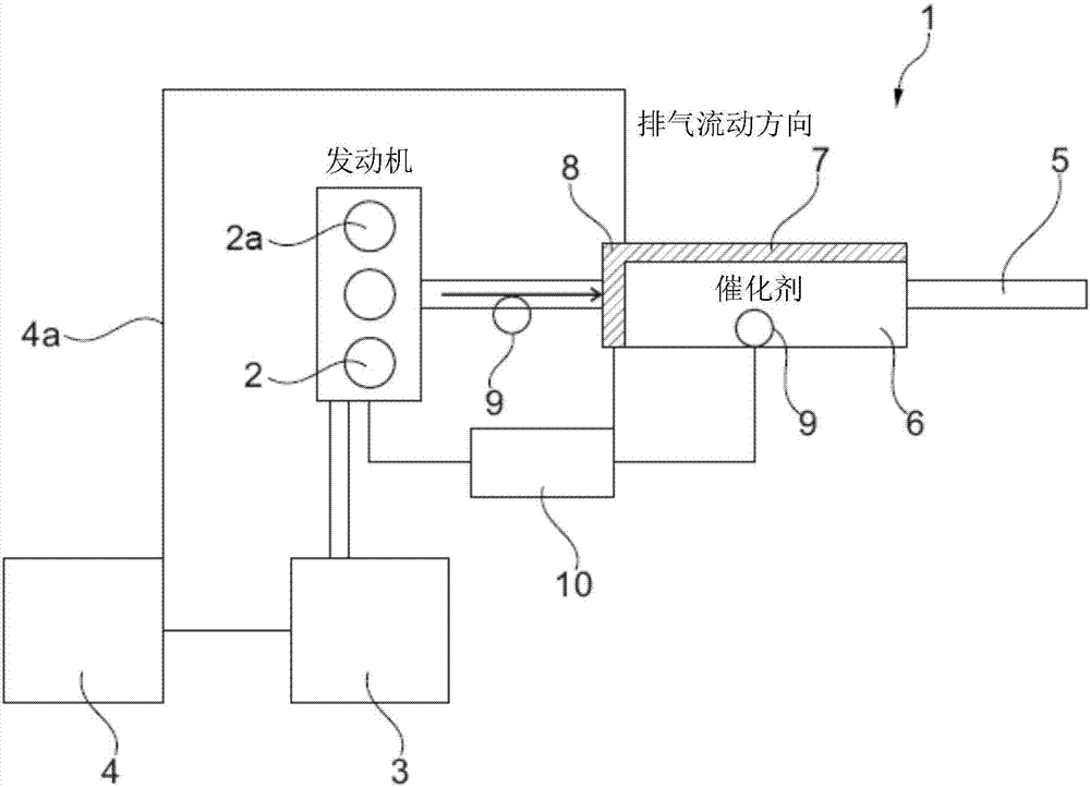
[0027] according to figure 1 The illustrated device 1 comprises an internal combustion engine 2, which may be a self-ignition internal combustion engine or an external ignition internal combustion engine. The internal combustion engine 2 has three cylinders 2a, but can alternatively also have 2, 4, 5, 6 or 8 cylinders. The internal combustion engine 2 is further connected to a generator 3 for charging a first rechargeable battery 4 of the motor vehicle. An exhaust passage 5 is connected to the internal combustion engine 2 so as to discharge exhaust gas. An exhaust aftertreatment system 6 is arranged in the exhaust passage 5 . The exhaust gas aftertreatment system 6 contains at least one catalytic converter 7 , such as an oxidation catalytic converter, a particulate filter, a nitrogen oxide storage catalytic converter and / or a catalytic converter for selective catalytic reduction.

[0028] The electric heating device 8 is arranged in connection with the catalytic converter 7...


PUM


Abstract

The present invention provides a method for controlling an exhaust gas purification system in a motor vehicle comprising a hybrid drive unit comprising an internal combustion engine and an electric motor in which the temperature of the catalytic converter is controlled by electrical heating apparatus and the exhaust temperature are adjusted so that the rechargeable battery of the motor vehicle reaches a charged state due to the operation of the heating device, and the charge state is best suited for the purpose of recharging under the operation state of the internal combustion engine, increasing the torque while providing exhaust gas for operating the catalytic converter at a suitably high temperature.

Description

technical field [0001] The invention relates to a method for controlling an exhaust gas purification system in a motor vehicle comprising a hybrid drive unit, wherein the catalytic converter is brought to its operating temperature selectively electrically or by increasing the temperature of the exhaust gas. Background technique [0002] Internal combustion engines require an exhaust gas purification system comprising one or more catalytic converters in order to purify the exhaust gas produced by said internal combustion engine. Exhaust gas catalytic converters, such as oxidation catalytic converters, nitrogen oxide storage catalytic converters, catalytic converters for selective catalytic reduction, etc., require specific operating temperatures in order to operate efficiently. However, when starting the internal combustion engine, the exhaust gas - whose temperature is normally used to reach the operating temperature of the catalytic converter - is still relatively cool. ...

Claims


Application Information

Patent Timeline
IPC IPC(8): F01N9/00F01N3/20F01N3/027
CPCF01N3/027F01N3/2013F01N9/00F01N9/002F01N2900/1404F01N2900/1602F01N2590/11F01N2900/104B60K6/48B60W10/06B60W10/08B60K2006/4825B60W2510/244B60W20/16Y02T10/40Y02T10/62
Inventor 弗雷德里克·德·斯梅特莫尼卡·昂斯特丹尼尔·罗特格
Owner FORD GLOBAL TECH LLC
Learn More