Environment-friendly efficient pyrolysis device for garbage

A garbage and environmental protection technology, applied in the field of garbage environmental protection and high-efficiency pyrolysis device, can solve the problems of high cost of garbage incineration, poor practicability, secondary pollution of dioxin-like substances, etc., and achieve the effect of preventing dioxin-like substances

Inactive Publication Date: 2017-06-30
甘培嘉
View PDF4 Cites 0 Cited by
  • Summary
  • Abstract
  • Description
  • Claims
  • Application Information

AI Technical Summary

Problems solved by technology

But the existing waste incineration pyrolysis treatment device has the following disadvantages: the one is that the incineration process of the existing waste incineration pyrolysis device will generate a large amount of dioxins
Dioxin treatment is difficult and expensive
Although the research and understanding of dioxin-like substances have been deepened in recent years, technically through the "3T" control of incinerators and strict incineration flue gas purification process, the emission of dioxin-like substances can be controlled within strict standards However, the one-time investment and operating costs are greatly increased, and the dioxin-like substances removed by flue gas purification still have secondary pollution
[0003] Second, the existing waste incineration pyrolysis device requires a lot of auxiliary energy, but the utilization efficiency of the heat generated by waste incineration itself is not high enough, resulting in high cost of waste incineration
[0004] Third, the structure of the existing incineration device is complex, the manufacturing cost is high, the one-time investment for purchase and use is large, and the project construction takes a long period of funds
However, these technologies have a large one-time investment, high operating costs, unsatisfactory effects, and poor practicability

Method used


Image

  • Environment-friendly efficient pyrolysis device for garbage

Examples


Embodiment 1

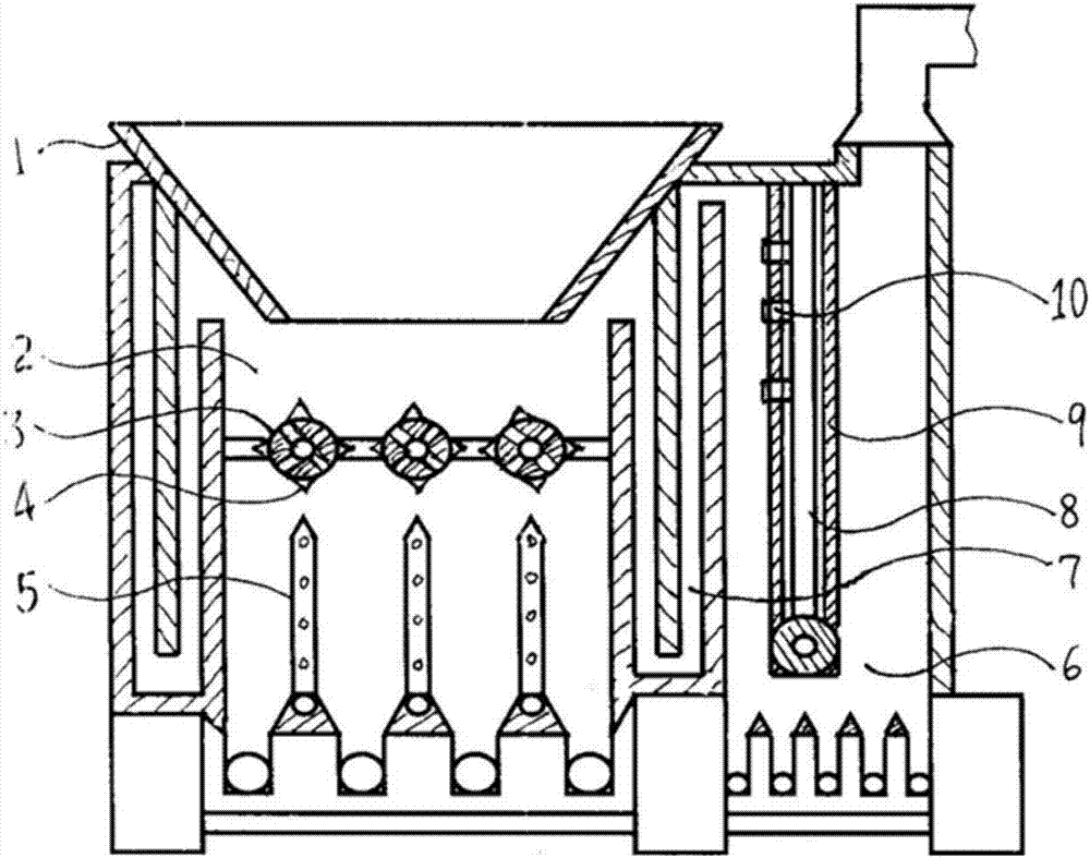
[0027] Embodiment 1 As shown in the accompanying drawing, the garbage environmental protection and high-efficiency pyrolysis device of the present invention includes a garbage input mechanism 1 with a garbage inlet. The gas channel 7 communicates with the secondary pyrolysis chamber 6, and the primary pyrolysis chamber 2 is provided with a primary thermal decomposition air conveying mechanism, which has a number of horizontally arranged hot air pipes 3 arranged at intervals and vertical heat pipes below them. The air pipe 5 and the horizontally placed hot air pipe 3 form a rotatable connection with the power mechanism. The horizontally placed hot air pipe 3 is provided with convex spines 4. The mechanism has a number of hot air nozzles 8 arranged at intervals, a connection mechanism is provided between the hot air nozzles 8, and a protective wall 9 is provided outside the hot air nozzles 8, and the hot air nozzle 8 has a nozzle extending out of the protective wall 9 10.

[00...


PUM


Abstract

The invention discloses an environment-friendly and high-efficiency pyrolysis device for garbage. In order to overcome the disadvantages of existing garbage pyrolysis that easily generates dioxins to pollute the environment, poor pyrolysis effect, high processing and operating costs, the garbage input mechanism of the present invention is connected with the primary pyrolysis chamber, and the primary pyrolysis chamber is connected with the secondary pyrolysis chamber , a number of horizontal hot air pipes and vertical hot air pipes below are arranged at intervals in the primary pyrolysis chamber, and the horizontal hot air pipes form a rotatable connection with the power mechanism. Protruding spines are provided, several hot air nozzles are arranged at intervals in the secondary pyrolysis chamber, and protective walls are arranged outside the hot air nozzles. The invention is used to treat domestic waste, medical waste, etc. It does not generate dioxins by incinerating and pyrolyzing waste, which can save the cost of dioxin treatment and auxiliary fuel, and has simplified structure, low manufacturing and use costs, and is suitable for waste incineration and pyrolysis treatment. Fast and thorough, good effect, high efficiency and benefit.

Description

technical field [0001] The invention relates to a garbage harmless treatment device, in particular to an environmentally friendly and efficient pyrolysis device for garbage. Background technique [0002] Waste incineration pyrolysis is a high-temperature thermochemical treatment technology. The combustible components in the waste react with oxygen in the air in the incinerator and are converted into high-temperature gases and solid residues. The pyrolysis process of waste incineration produces a large amount of heat energy, which can reduce the volume by 80%-90%. It can destroy the composition and structure of harmful solid waste, kill pathogenic bacteria, and achieve the purpose of detoxification and detoxification. It has the advantages of reduction, harmlessness and resource utilization. It is one of the waste treatment methods widely used in developed countries. In Japan and other countries where arable land is scarce, the proportion of waste incineration and pyrolysis t...

Claims


Application Information

Patent Timeline
Patent Type & Authority Applications(China)
IPC IPC(8): F23G5/027F23G5/16
CPCF23G5/0276F23G5/16F23G2201/302F23G2201/303F23G2202/103F23G2207/30
Inventor 甘培嘉
Owner 甘培嘉
Why Eureka
Try Eureka