
Ultralow-sidelobe pulse compression method

A technology of pulse compression and ultra-low sidelobe, applied to radio wave measurement systems, instruments, etc., can solve the problems of reducing radar detection distance resolution, reducing radar action distance, affecting distance resolution and signal detection capabilities, etc., to ensure Ultra-low sidelobe performance, reduce sidelobe, reduce the effect of target flicker

Inactive Publication Date: 2017-06-30
四川九洲空管科技有限责任公司
View PDF4 Cites 18 Cited by
  • Summary
  • Abstract
  • Description
  • Claims
  • Application Information

AI Technical Summary

Problems solved by technology

Weighting the window function can reduce the side lobe, but it will inevitably widen the main lobe, sacrificing a certain range resolution and signal-to-noise ratio. The broadening of the main lobe will reduce the resolution of the radar detection distance, and the loss of signal-to-noise ratio will be reduced. Radar Range
In order to reduce the influence of the sidelobe after matched filtering on the system performance, it is necessary to obtain the optimal amplitude-frequency characteristic function, which can minimize the impact on the distance resolution and signal detection ability while suppressing the sidelobe signal causing interference.

Method used


Image

  • Ultralow-sidelobe pulse compression method

Examples


Embodiment Construction

[0037] The present invention will be further described below in conjunction with the accompanying drawings.

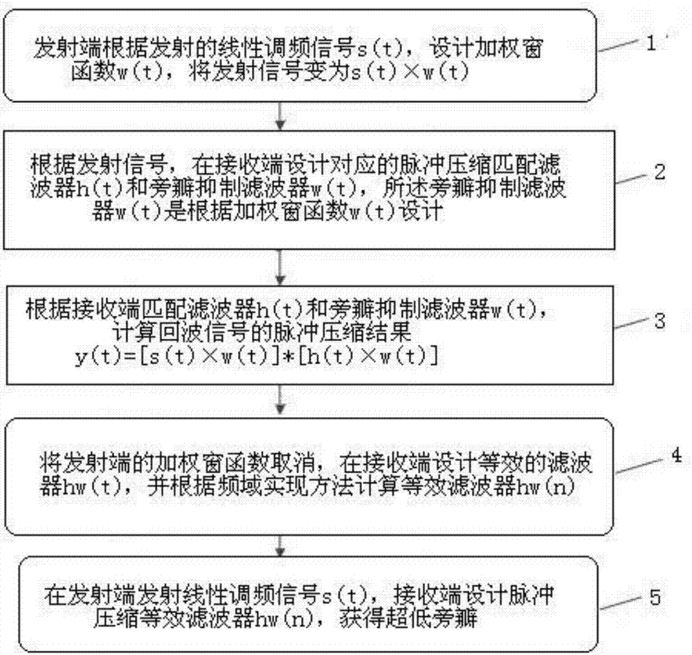
[0038] like figure 1 As shown, an ultra-low sidelobe pulse compression method specifically includes the following process:

[0039] Step 1. The transmitter designs a weighted window function w(t) according to the transmitted chirp signal s(t), and changes the transmitted signal to s(t)×w(t);

[0040] Step 2, according to the transmitted signal, design the corresponding pulse compression matched filter h(t) and sidelobe suppression filter w(t) at the receiving end, and the sidelobe suppression filter w(t) is based on the weighted window function w (t) design;

[0041] Step 3, calculate the pulse compression result y(t)=[s(t)×w(t)]*[ h(t)×w(t)];

[0042] Step 4. Cancel the weighted window function at the transmitter, and design an equivalent filter h at the receiver w (t), and calculate the equivalent filter h according to the frequency domain implementation method ...


PUM


Abstract

The invention relates to the technical field of digital signal processing, and discloses an ultralow-sidelobe pulse compression method. The method specifically comprises the following steps: S1, a transmitter designs a weighted window function w(t) according to a transmitted linear frequency modulation signal s (t), and converts the transmitted signal into s(t)*w(t); S2, a corresponding pulse compression matched filter h(t) and a corresponding sidelobe suppression filter w(t) are designed at a receiver according to the transmitted signal, wherein the sidelobe suppression filter w(t) is designed according to the weighted window function w(t); S3, the pulse compression result y(t)=[s(t)*w(t)]*[h(t)*w(t)] of an echo signal is calculated according to the matched filter h(t) and the sidelobe suppression filter w(t) at the receiver; S4, the weighted window function at the transmitter is cancelled, an equivalent filter hw(t) is designed at the receiver, and an equivalent filter hw(n) is calculated according to a frequency domain implementation method; and S5, the transmitter transmits the linear frequency modulation signal s(t), the receiver designs a pulse compression equivalent filter hw(n), and ultralow sidelobe is obtained. By adding window functions at the transmitter and the receiver respectively, sidelobe is reduced effectively.

Description

technical field [0001] The invention relates to the technical field of digital signal processing, in particular to an ultra-low sidelobe pulse compression method. Background technique [0002] Surface surveillance radar is a radar that monitors ground moving targets or fixed obstacles such as aircraft and vehicles in the flight area of ​​the airport. It helps the controllers of towers and aprons to clearly understand the positions of ground aircraft and vehicles with the help of surface surveillance radar displays, and provides complex information for airports. The changing situation provides 24 / 7 status awareness. [0003] The surface surveillance radar requires a coverage range of 6km and a distance resolution of 12m. According to the calculation of the radar equation, in order to increase the radar range, it is necessary to increase the radar transmission energy. Wide transmit signal, and the increase of pulse power is limited by the hardware system, and only increasing ...

Claims


Application Information

Patent Timeline
Patent Type & Authority Applications(China)
IPC IPC(8): G01S7/28
CPCG01S7/2813
Inventor 张炼皈勇刘元春
Owner 四川九洲空管科技有限责任公司
Learn More