Unmanned vehicle real-time positioning method based on laser reflection strength

A technology of laser reflection and real-time positioning, which is applied in the direction of radio wave measurement systems and instruments, can solve the problems of positioning algorithm failure and false detection, and achieve the effect of high detection accuracy and reduced calculation amount

Active Publication Date: 2017-06-30
TONGJI UNIV
4 Cites 62 Cited by

AI-Extracted Technical Summary

Problems solved by technology

[0008] Although the positioning algorithm based on the feature level has the advantages of simple structure and low computational complexity, there are some limitations when it is applied to the positioning of unmanned vehicles and the estimation of the state of nonlinear systems in complex environments.
When an...

Method used

A kind of unmanned vehicle real-time positioning method based on laser reflection intensity, this method first extracts laser reflection intensity feature from the laser point cloud data of single frame, according to vehicle kinematics model, the roadside feature of multi-frame detection The point coordinates are converted to the current unmanned vehicle coordinate system, and then the reflection intensity distribution is matched with the reflection intensit...

Abstract

The invention relates to an unmanned vehicle real-time positioning method based on laser reflection strength. The method comprises the following steps of S1, photographing two sides of a city road by an on-vehicle laser radar, obtaining a plurality of frames of point cloud data, extracting road edge points and converting the road edge points into a current vehicle coordinate system; S2, selecting the road edge points of which the z-axis coordinate value is in a preset range and obtaining coordinates of the road edge points in a GPS coordinate system, using the current GPS coordinate point of the unmanned vehicle as an original point, dividing a coordinate space for obtaining a grid map; S3, matching the gridded high-precision map with the grid map which is obtained in the step S2, thereby obtaining position of the unmanned vehicle on a high-precision map; and S4, predicating vehicle posture by means of a Kalman filter. Compared with prior art, the unmanned vehicle real-time positioning method can realize real-time accurate positioning in a complicated environment and can effectively improve driving safety of the unmanned aerial vehicle.

Application Domain

Technology Topic

Image

  • Unmanned vehicle real-time positioning method based on laser reflection strength
  • Unmanned vehicle real-time positioning method based on laser reflection strength
  • Unmanned vehicle real-time positioning method based on laser reflection strength

Examples

  • Experimental program(1)

Example Embodiment

[0034] Example
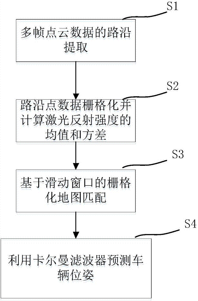
[0035] A real-time positioning method for unmanned vehicles based on laser reflection intensity. The method first extracts the laser reflection intensity characteristics from the laser point cloud data of a single frame, and converts the coordinates of the road edge feature points detected in multiple frames according to the vehicle kinematics model Go to the current unmanned vehicle coordinate system, and then use the regional probability matching search algorithm to match the reflection intensity distribution with the reflection intensity distribution in the high-precision map, and calculate the current unmanned vehicle's lateral, longitudinal and heading angle deviations as the observation values , Input to Kalman filter for pose estimation. This embodiment is both innovative and practical, can realize real-time accurate positioning in a complex environment, and can effectively improve the safety of unmanned vehicles.
[0036] Specific steps are as follows:
[0037] 1. Roadside feature point detection
[0038] The Velodyne HDL-32E lidar is used as the environmental sensor. Adopting a roadside detection algorithm based on the spatial characteristics of point cloud data. First, in most urban environments, the height of roadsides has a uniform standard, generally 10-15cm higher than the road surface. Secondly, in the Cartesian coordinate system, the roadside The height changes drastically along the z-axis. According to these spatial features, the edge extraction of single frame point cloud data is performed, and the detection results are as follows figure 2 Shown.
[0039] Since the density of the road edge feature points detected in a single frame decreases with the increase of the detection distance, in order to obtain a complete description of the road edge, it is necessary to convert the road edges detected in multiple frames to the same coordinate system. Since the sensor coordinate system changes with the movement of the unmanned vehicle, the vehicle-mounted inertial navigation system is used to obtain the displacement and heading angle change of the vehicle in two adjacent frames. x , D y And d θ , The feature point of the road edge of a single frame is expressed as Q k , Where Q k =(x k ,y k ) Is the road edge coordinates of the kth frame. Therefore, the multi-frame road edges in the current vehicle coordinate system are:
[0040] R=[Q k f(Q k-1 ) f 2 (Q k-2 ) ... f n (Q k-n )]
[0041]
[0042]
[0043] The result is image 3 Shown.
[0044] 2. Laser point cloud reflection intensity map generation
[0045] First, take the point cloud with the z axis less than -1.8m for the height information of each frame of point cloud, save 20 frames of local coordinate data of the ground point cloud through inertial navigation data, and use Gaussian back projection to project it to GPS coordinates.
[0046] Create a 200x200 raster map with the current time latitude, longitude and heading angle as the origin. The detection distance is -25-25m, and the accuracy of each raster map is approximately equal to 0.25m. Then, the converted GPS coordinates of the point cloud are projected onto the grid map, and the mean value, variance, and number of point clouds of the reflection intensity falling into each grid are calculated. By traversing the generated raster map, all the raster coordinates that fall into the grid points greater than 60 are calculated to provide information for the subsequent raster map matching.
[0047] 3. Raster map matching based on sliding window
[0048] The purpose of map matching is to estimate the deviation between the detected road edges and the high-precision map data. The sliding window search method is an algorithm used to estimate the positional relationship between two raster images. When the GPS coordinates of the current vehicle are the origin and the heading angle is the positive direction of the y-axis, take out multiple 200x200 raster images from the map (the offset of the origin of each raster image is from left to right -0.5m~0.5m, front and back. Offset -2.0m~2.0m, that is, find the position with the highest matching degree in the search area within the left and right -0.5~0.5 and front and back -2.0~2.0).
[0049] In each grid image taken from the map, find all grids with the same coordinates as in step 2. Each grid includes the mean and variance of the reflection intensity. The Gaussian similarity formula is used to calculate the direct similarity of the two raster images, and the weighting algorithm is used to obtain the position deviation after matching.
[0050] 4. Positioning
[0051] After the edge matching algorithm and the sliding window matching algorithm, the transformation matrix T is obtained, Where θ, t x , T y They are the heading angle, the offset in the x direction and the offset in the y direction obtained by map matching. In the second Kalman filter, these three quantities are used as the observation value of the Kalman filter. Two Kalman filters are used to filter the noise and estimate a relatively accurate position information. Denote the vehicle position at time t as According to vehicle kinematics, predict the vehicle pose at t+1:
[0052]
[0053] among them Is the predicted vehicle pose and Δt is the time interval.
[0054] The first Kalman filter is used to fuse GPS measurements and predictions. The second Kalman filter is used to fuse the transformation matrix T and the output value of the first Kalman filter.

PUM

no PUM

Description & Claims & Application Information

We can also present the details of the Description, Claims and Application information to help users get a comprehensive understanding of the technical details of the patent, such as background art, summary of invention, brief description of drawings, description of embodiments, and other original content. On the other hand, users can also determine the specific scope of protection of the technology through the list of claims; as well as understand the changes in the life cycle of the technology with the presentation of the patent timeline. Login to view more.

Similar technology patents

Classification and recommendation of technical efficacy words

  • Improve detection accuracy
  • Small amount of calculation

Gait recognition method based on inertial sensor

ActiveCN104729507AAdd cycle division stageSmall amount of calculationNavigation by speed/acceleration measurementsSport trainingWave phenomenon
Owner:DALIAN UNIV OF TECH
Why Eureka
Try Eureka