
Cantilever base punching die

A technology of punching die and wrist arm, which is applied in the field of punching die of wrist arm base, can solve the problems of complex process, troublesome forming, low precision, etc., and achieve the effects of convenient connection, smooth unloading and convenient punching

Inactive Publication Date: 2017-07-04
CHANGLI FORGING
View PDF0 Cites 0 Cited by
  • Summary
  • Abstract
  • Description
  • Claims
  • Application Information

AI Technical Summary

Problems solved by technology

[0003] The purpose of the present invention is to overcome the defects of complicated process, troublesome formation and low precision in processing the base of the wrist arm in the prior art. A punching die for the base of the wrist arm is designed. The female mold is fixed conveniently and reliably, and the fixing plate is connected conveniently and reliably , convenient punching, smooth unloading, and reliable fixing of the unloading plate

Method used


Image

  • Cantilever base punching die
  • Cantilever base punching die

Examples


Embodiment Construction

[0015] In order to make the technical means, creative features, goals and effects achieved by the present invention easy to understand, the present invention will be further described below in conjunction with specific illustrations.

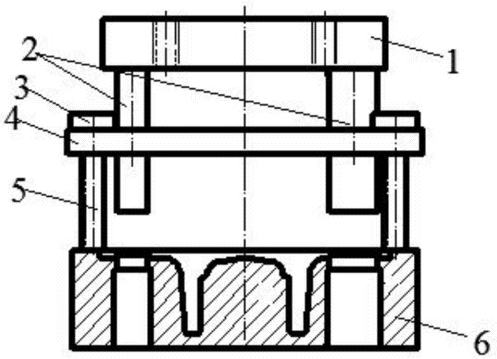
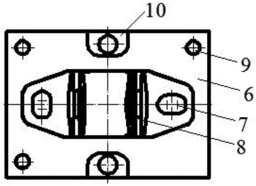
[0016] A wrist-arm base punching die, comprising a fixed plate 1, a punch 2, a bolt 3, a discharge plate 4, a branch pipe 5, a female mold 6, a forming hole 7, a female mold groove 8, a cylindrical hole 9, and a counterbore 10, The punch 2 is fixed on the left and right ends of the bottom surface of the fixed plate 1, the branch pipe 5 is fixed on the unloading plate 4 by bolts 3, the branch pipe 5 supports the unloading plate 4 on the top of the die 6, and the base of the die 6 is a cuboid, In the middle of the upper surface of the female mold 6, a female groove 8 is processed, and the protruding part of the wrist arm is promptly packed into the female groove 8. A counterbore 10 is respectively processed before and after the middle of the upper ...


PUM


Abstract

The invention discloses a cantilever base punching die and belongs to the technical field of die design. The punching die comprises a fixing plate, puncher chips, bolts, a discharging plate, branch pipes, a female die body, forming holes, a female die groove, cylindrical holes and counter bores. The puncher chips are fixed to the left end and the right end of the bottom face of the fixing plate. The branch pipes are fixed to the discharging plate through the bolts and support the discharging plate to the upper portion of the female die body. A basic body of the female die body is cuboid. The female die groove is machined in the center of the upper surface of the female die body. A protruding part of a cantilever is mounted in the female die groove. The counter bores are formed in the upper portion and the rear portion of the middle of the upper surface of the female die body correspondingly. Through holes are drilled in the middles of the counter bores. The female die body is fixed to a machine tool by enabling connecting pieces to penetrate through the through holes, and fixing is convenient and reliable. According to the cantilever base punching die disclosed by the invention, the fixing plate is convenientlyconnected and reliably fixed, punching is convenient, discharging is smooth, and the discharging plate is reliably fixed.

Description

technical field [0001] The invention relates to the technical field of die design, in particular to a punching die for a wrist arm base. Background technique [0002] Some auxiliary parts often used in vehicles and mechanical equipment have irregular shapes. The wrist arm base is a common type of such parts. The traditional processing methods of these parts are mostly casting. The processing efficiency of this processing method The precision and accuracy are very low, and it is easy to cause damage to other important parts in vehicles and mechanical equipment. These parts can also be processed by forging. The previous forging die was troublesome in forming due to unreasonable structural design, low die strength and low precision. , affect the service life of the transmission parts, and the cost is high, so design a punching die for the base of the wrist arm base that is convenient and reliable to fix, the fixed plate is convenient to connect, reliable to fix, convenient to p...

Claims


Application Information

Patent Timeline
Patent Type & Authority Applications(China)
IPC IPC(8): B21D28/34B21D45/08
CPCB21D28/34B21D45/08
Inventor 杨奎琦
Owner CHANGLI FORGING
Learn More