
Bladeless impeller for steam turbine, rotor and multi-channel steam turbine

A steam turbine rotor, blade impeller technology, applied in the direction of machine/engine, stator, mechanical equipment, etc., can solve problems such as blade breakage, achieve the effect of eliminating axial force, preventing breakage, reducing difficulty and manufacturing cost

Active Publication Date: 2017-07-04
陈晓兵
View PDF7 Cites 0 Cited by
  • Summary
  • Abstract
  • Description
  • Claims
  • Application Information

AI Technical Summary

Problems solved by technology

[0005] This application provides a steam turbine bladeless impeller, rotor and multi-channel steam turbine to solve the problem that the blades are broken due to excessive centrifugal force when the traditional bladed impeller rotates at high speed

Method used


Image

  • Bladeless impeller for steam turbine, rotor and multi-channel steam turbine
  • Bladeless impeller for steam turbine, rotor and multi-channel steam turbine
  • Bladeless impeller for steam turbine, rotor and multi-channel steam turbine

Examples


Embodiment Construction

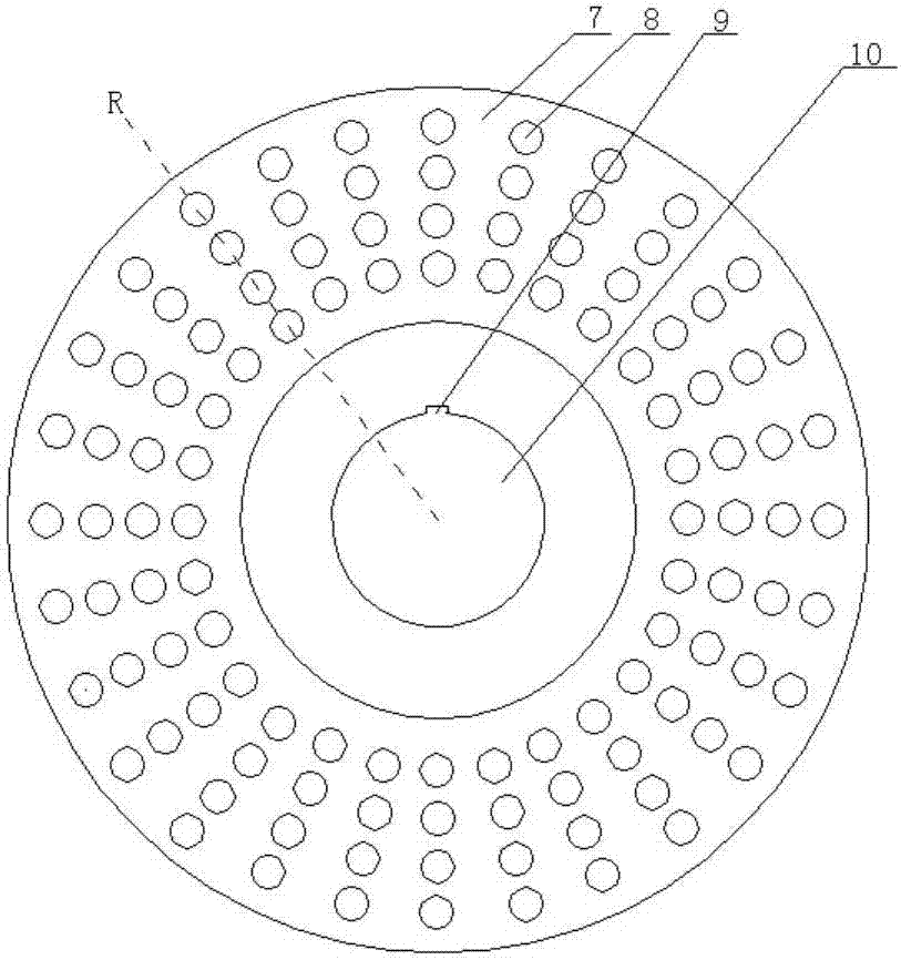
[0059] In the first aspect, the embodiment of the present application provides a bladeless impeller of a steam turbine, which includes a disc 7 provided with several rows of steam holes, and each row of steam holes includes at least one steam hole 8;

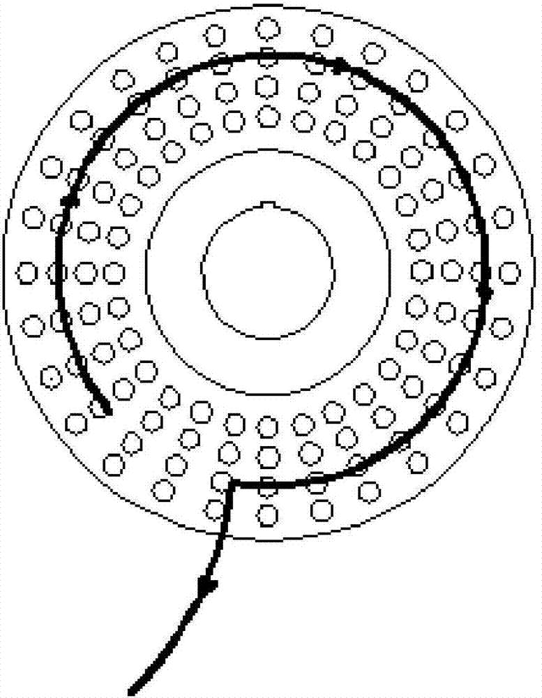
[0060] The series of steam holes surround the center of the disk 7 and are arranged circumferentially on the surface of the disk 7;

[0061] The series of steam hole groups are used to obtain energy from steam to make the disc 7 rotate.

[0062] The center of the disc 7 may be provided with a main shaft hole 10 and a keyway 9 communicating with the main shaft hole.

[0063] When each steam hole group includes a plurality of steam holes 8, such as figure 2 As shown, a plurality of steam holes 8 in the same steam hole group can be radially arranged along the radius R of the disk 7 and extend from the center of the disk 7 to the outer edge of the disk 7 . The above content is illustrative, the number of rows of steam hole groups...


PUM


Abstract

The application provides a bladeless impeller for a steam turbine, a rotor and a multi-channel steam turbine. The bladeless impeller for the steam turbine comprises a disk provided with a plurality of columns of steam hole groups, wherein each column of steam hole groups comprises at least one steam hole; the plurality of columns of steam hole groups surround the center of the disk, and are arranged circumferentially on the surface of the disk. A nozzle group arranged on a steam inlet space ring sprays out steam, and the flow direction of stream is changed forcibly under the limitations of the inner walls of the steam holes, so that torsion is generated on the inner walls of the steam holes in order to drive the rotor to rotate. Thus, a movable blade and a baffle plate are not needed, and the phenomenon of fracture of the movable blade in the conventional steam turbine can be prevented effectively, thereby shortening maintenance time and lowering maintenance cost; under the situation of having the same power with the conventional impeller type steam turbine, the size of the steam turbine can be reduced greatly, and meanwhile the difficulty of a manufacturing process and the manufacturing cost are lowered; moreover, the stream does not produce axial force on the impeller, so that axial acting force between the impeller and a main shaft is eliminated, the durability of the rotor is enhanced, and stream energy loss is reduced.

Description

technical field [0001] The present application relates to the field of power equipment, in particular to a bladeless impeller of a steam turbine, a rotor and a multi-channel steam turbine. Background technique [0002] The steam turbine is a power equipment that uses high-temperature steam as the working medium to convert the thermal energy of the steam into mechanical energy. It is mainly used to drive various pumps, blowers, compressors and generators in industrial processes. Although there are many types of steam turbines, the basic structure is roughly the same. [0003] see figure 1 , the traditional vane steam turbine mainly includes cylinder 1, stator and rotor; cylinder 1 separates the steam turbine from the external steam to form a closed steam chamber; The plate 2 and the nozzle 3 fixed on the partition 2; the rotor includes the main shaft 6 arranged longitudinally along the steam chamber, the wheel disc 5 installed on the main shaft 6 and the moving blade 4 fixe...

Claims


Application Information

Patent Timeline
Patent Type & Authority Applications(China)
IPC IPC(8): F01D1/34F01D9/04
CPCF01D1/34F01D9/04
Inventor 陈晓兵
Owner 陈晓兵
Learn More