Rapid thermal response composite phase change heat storage device and preparation method thereof

A composite phase change and heat storage technology, which is applied in chemical instruments and methods, heat storage equipment, indirect heat exchangers, etc., can solve the problems of long thermal response time of phase change, long thermal response time, and low heat dissipation efficiency. Achieve the effects of short phase change thermal response time, high thermal conductivity, and improved thermal conductivity

Active Publication Date: 2019-06-28
10TH RES INST OF CETC
View PDF4 Cites 0 Cited by
  • Summary
  • Abstract
  • Description
  • Claims
  • Application Information

AI Technical Summary

Problems solved by technology

[0009] In order to meet the short-term and high-efficiency heat dissipation requirements of the key components of the phased array radar in the supersonic aerospace vehicle, the purpose of the present invention is to address the shortcomings of the existing phase change heat storage, such as low thermal conductivity of phase change materials and long phase change thermal response time. To provide a phase change heat storage device with high thermal conductivity of phase change material, short phase change heat response time, strong heat storage capacity, and strong shock and vibration resistance; and good sealing, which can solve the problem of single phase change paraffin preparation Preparation method of fast thermal response composite phase change heat storage with long thermal response time and low heat dissipation efficiency of variable heat storage

Method used


Image

  • Rapid thermal response composite phase change heat storage device and preparation method thereof
  • Rapid thermal response composite phase change heat storage device and preparation method thereof
  • Rapid thermal response composite phase change heat storage device and preparation method thereof

Examples


Embodiment Construction

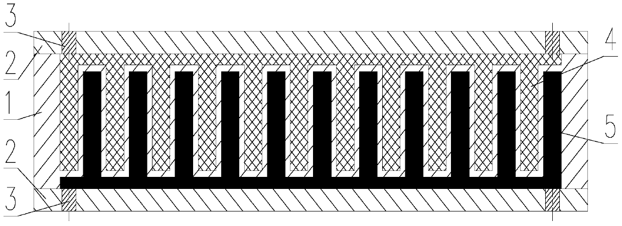
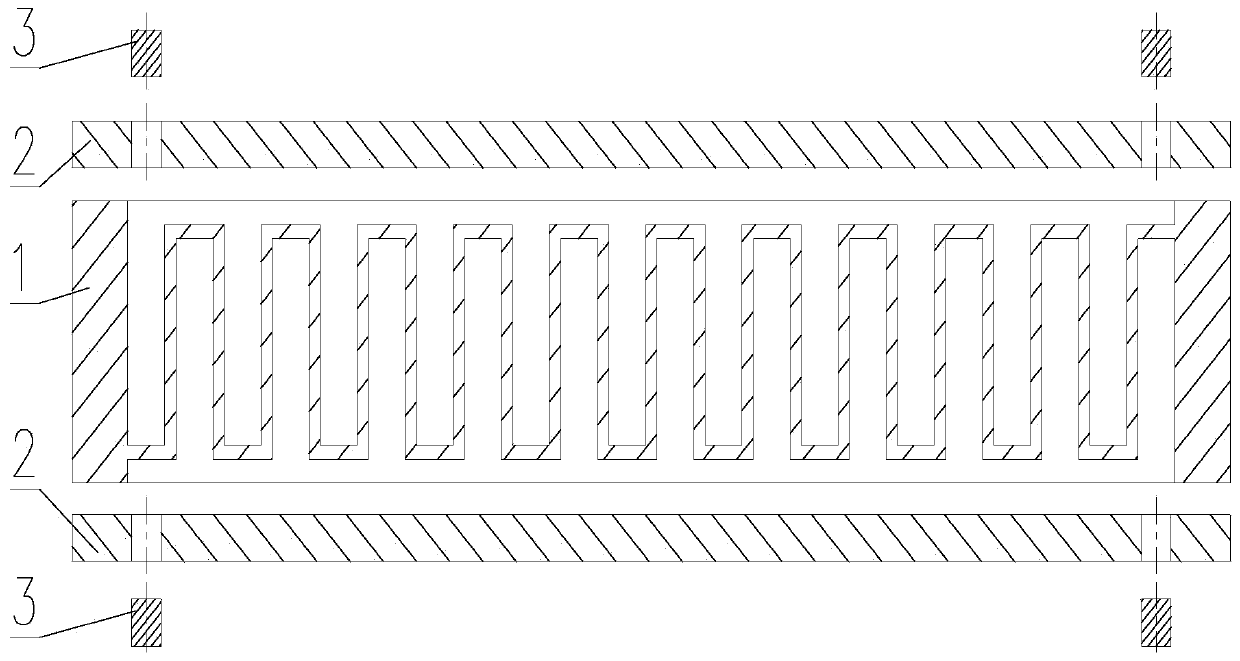
[0024] refer to Figure 1 ~ Figure 3 . In the embodiment described below, a rapid thermal response composite phase change heat storage device is composed of a heat storage container 1, an encapsulation cover plate 2, a sealing column 3, a phase change paraffin wax 4 and a phase change alloy 5. The heat storage container of phase-change paraffin and phase-change alloy, the inner cavity of the heat storage container is made of forward and reverse continuous U-shaped cooling groove cavities formed in series in a linear array sequence, wherein the forward U-shaped cooling cavity is used as a paraffin cavity, The phase-change paraffin wax 4 is poured, and the reverse U-shaped heat dissipation chamber is used as an alloy chamber, and it is filled with a phase-change alloy 5 with a thermal conductivity ≥ 15W / (m K) and a high thermal conductivity, and is sealed by the upper and lower packaging cover plates 2. High thermal conductivity phase change alloy is integrated with high enthal...


PUM

PropertyMeasurementUnit
phase transition temperatureaaaaaaaaaa
pore sizeaaaaaaaaaa
phase transition temperatureaaaaaaaaaa

Abstract

The invention provides a quick thermal response composite phase change heat reservoir and a preparation method thereof, and can solve the problems of long thermal response time and low heat dissipating efficiency of a phase change heat reservoir prepared by single phase change paraffin. The quick thermal response composite phase change heat reservoir is realized through the following methods: forward and reverse continuous U-shaped heat dissipating groove cavities serially connected in a linear array sequence are formed in an inner cavity of a heat storage container; the forward U-shaped heat dissipating cavity serves as a paraffin cavity filled with phase change paraffin (4); the reverse U-shaped heat dissipating cavity serves as an alloy cavity filled with a phase change alloy (5); the high-heat-conductivity phase change alloy and the high-enthalpy-value phase change paraffin are sealed as a whole through sealing of upper and lower sealing cover plates (2); and a phase change paraffin and phase change alloy filling port of the heat reservoir is further welded through laser to realize preparation of the quick thermal response composite phase change heat reservoir. The high-efficiency heat transfer of the phase change heat reservoir is realized by the combined effect of the high-heat-conductivity phase change alloy with the heat conducting coefficient of being not less than 15 W / (m. K) and the high-heat-conductivity aluminum alloy of the phase change heat reservoir.

Description

technical field [0001] The invention relates to a preparation method of a rapid thermal response composite phase change heat storage device Background technique [0002] With the rapid development of the "high-speed aircraft" business, supersonic aerospace vehicles have an urgent need for high-power phased array radar. Supersonic aerospace vehicles are fast and have a long range. The long-term high-speed flight leads to extremely harsh working environment for phased array radars. The working environment temperature is as high as 80°C, while high-power phased array The heat flux density of the local hot spot on the chip reaches 100W / cm 2 Above, the high temperature will cause the performance of the chip to drop sharply or even burn out, which will lead to unstable gain of the phased array antenna, poor amplitude and phase consistency, and even phased array radar failure. Due to its own conditions, phased array radar TR components cannot be cooled by natural convection, forc...

Claims


Application Information

Patent Timeline
Patent Type & Authority Patents(China)
IPC IPC(8): F28D20/02C09K5/06B23K28/02
CPCB23K28/02B23K2101/14C09K5/063F28D20/021F28D20/02F28D20/025F28F21/081F28F2215/00Y02E60/14
Inventor 谢义水苏欣
Owner 10TH RES INST OF CETC
Why Eureka
Try Eureka