A designing and manufacturing method for a drop hammer type impact clamp allowing non-single impact positions

An impact position, drop weight technology, applied in the direction of using a single impact force to test the strength of materials, measuring devices, instruments, etc., can solve the problem that the position of the impact point cannot be adjusted.

Inactive Publication Date: 2017-07-04
TIANJIN POLYTECHNIC UNIV
View PDF6 Cites 7 Cited by
  • Summary
  • Abstract
  • Description
  • Claims
  • Application Information

AI Technical Summary

Problems solved by technology

[0004] Aiming at the problem that the position of the impact point of the existing impact test jig cannot be adjusted, th

Method used


Image

  • A designing and manufacturing method for a drop hammer type impact clamp allowing non-single impact positions
  • A designing and manufacturing method for a drop hammer type impact clamp allowing non-single impact positions
  • A designing and manufacturing method for a drop hammer type impact clamp allowing non-single impact positions

Examples


Embodiment 1

[0051] Such as Figure 4 As shown, this embodiment adopts a simple manual hinged clamp 101 in the compression module. Such as Figure 11 As shown, the hinge clamp chuck adopts the bolt chuck 1014 or the spring chuck 1012 . When the test design does not require the characterization of the pre-locking force, the easy-to-operate bolt chuck 1014 can be selected to perform the compression operation of the test piece.

[0052] If the test requires to characterize the pre-locking force of the hinge clamp on the test piece, the spring clamp 1012 is selected. The spring part 1011 of the collet adopts a helical metal compression spring. According to Hooke's law, the formula for calculating the locking force is:

[0053] F=-kx

[0054] Among them, k is the elastic coefficient of the spring, the negative sign indicates that the elastic force generated by the spring is opposite to the direction of the other compression itself, and x indicates the compression amount of the spring.

[0...

Embodiment 2

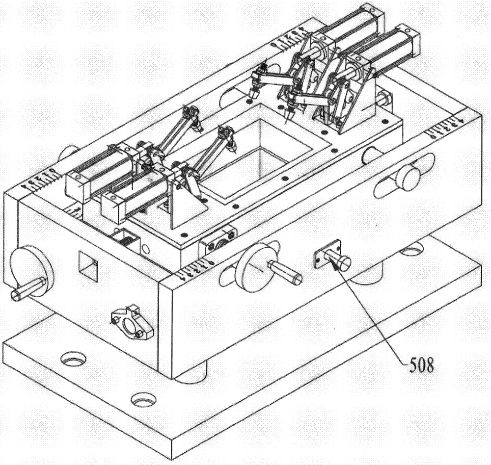
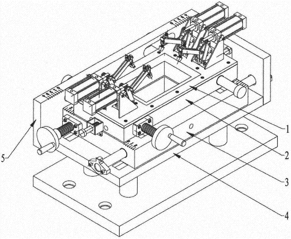
[0057] Such as Figure 5 As shown, the present embodiment employs a pneumatic hinge clamp 104 in the compression module. The compression and release of the articulated chuck is controlled by a cylinder. Similar to Embodiment 1, the pneumatic hinge chuck can use the bolt chuck 1014 or the spring chuck 1012 according to the test requirements. The test characterization method and pressure adjustment method are the same as in Example 1.

[0058] The above two embodiments propose two different schemes for the compression module of the present invention, and design two different types of chucks. Experimenters can choose the appropriate type of hinged clamps and clamps according to their needs when designing experiments.


PUM


Abstract

The invention discloses a designing and manufacturing method for a drop hammer type test clamp allowing non-single impact positions, relates to the fields of impact performance testing and evaluation for metal, nonmetal and composite materials, and particularly relates to designing and manufacturing of a plate-shaped test piece clamp allowing adjustable impact positions of a drop hammer type impact testing machine. Impact positions are fixed to the geometric centers of test pieces so that present drop hammer type impact testers cannot achieve impact performance testing or evaluation in a zone or a range of a material under practical service conditions. Aiming the problem, off-axis rolling screw transmission devices are adopted to drive horizontal and vertical moving modules to achieve bidirectional displacement, and are cooperated with positioning devices consisting of spring locking pins and limiting slide slots, and therefore accurate adjustment of a plurality of the impact positions on the test piece is achieved in a clamp mounting space limited by a drop hammer type tester, a drop hammer type impact test of non-fixed impact positions on the test piece is completed, and material impact performance under practical service conditions are tested and represented.

Description

technical field [0001] The invention relates to the field of impact performance testing and evaluation of metals, non-metals and composite materials, in particular to the design and manufacture of a plate-shaped specimen fixture of a drop weight impact testing machine with adjustable impact positions. Background technique [0002] Laminate structural composite materials have unique advantages such as light weight, high strength, fatigue resistance and good designability, and have been widely used in aviation, aerospace, transportation, construction and other fields. However, laminated structural composites also have fatal flaws that limit their development, that is, under low-energy impact, problems such as matrix cracking, fiber breakage, and interlayer delamination may occur inside or outside laminated structural composites. Especially under the condition of multiple reciprocating impacts, the accumulation of these damages will greatly reduce the post-impact compressive pr...

Claims


Application Information

Patent Timeline
IPC IPC(8): G01N3/04G01N3/30
CPCG01N3/04G01N3/30G01N2203/04
Inventor 张国利王志鹏马欢王伟伟陈光伟
Owner TIANJIN POLYTECHNIC UNIV
Why Eureka
Try Eureka