Radio frequency front end device

A radio frequency front-end and radio frequency connector technology, applied in the field of communication, can solve the problems of high design complexity and large PCB layout area, reduce the number of switches, reduce the PCB layout area and design complexity, save hardware costs and The effect of labor design cost

Inactive Publication Date: 2017-07-04
VIVO MOBILE COMM CO LTD
View PDF5 Cites 31 Cited by
  • Summary
  • Abstract
  • Description
  • Claims
  • Application Information

AI Technical Summary

Problems solved by technology

[0008] The present invention provides a radio frequency front-end device to solve the problems of large PCB layout area and high design complexity caused by the need to use three antennas and three switches in the existing inter-band uplink and downlink CA solutions

Method used


Image

  • Radio frequency front end device
  • Radio frequency front end device
  • Radio frequency front end device

Examples


Embodiment 1

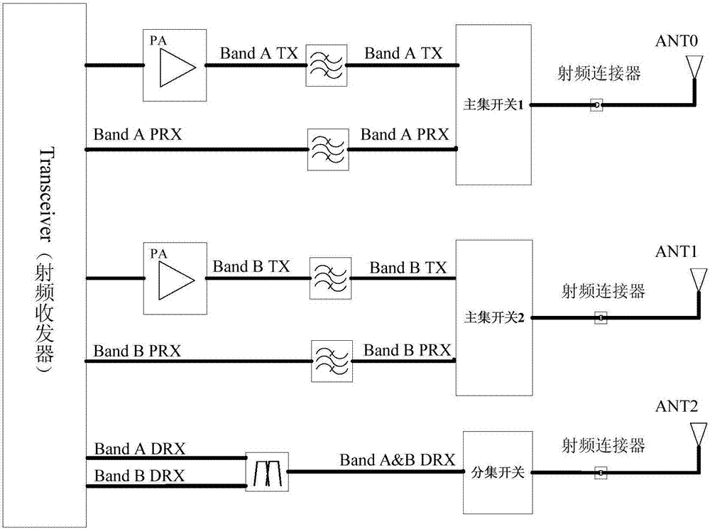
[0029] refer to Figure 4 , shows a schematic structural diagram of a radio frequency front-end device according to Embodiment 1 of the present invention.

[0030] The radio frequency front-end device of the embodiment of the present invention implements CA between uplink and downlink bands based on the time division mode of TDD. The uplink and downlink interband CA radio frequency front-end device of the embodiment of the present invention includes: a first radio frequency transceiver 101, a first PA102, a second PA103, a first switch 104, a second switch 105, a first bandpass filter 106, a second Bandpass filter 107, first double filter 108, second double filter 109, first radio frequency connector 110, second radio frequency connector 111, first antenna 112 and second antenna 113; first radio frequency transceiver 101 Including: the first frequency band signal transmitting pin, the second frequency band signal transmitting pin, the first frequency band main set signal rece...

Embodiment 2

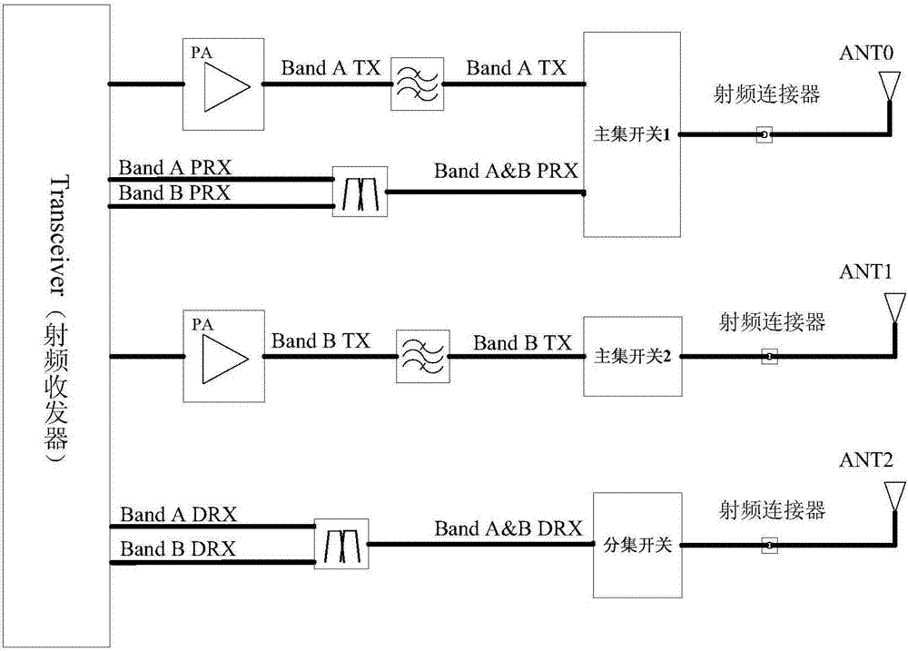
[0052] refer to Figure 5 , shows a schematic structural diagram of a radio frequency front-end device according to Embodiment 2 of the present invention.

[0053] The radio frequency front-end device of the embodiment of the present invention implements CA between uplink and downlink bands based on FDD frequency division mode. Since FDD works in frequency division mode, TX and RX are performed simultaneously, so TX of one frequency band and RX of two frequency bands are configured on the same antenna switch port, so as to realize that two antennas support uplink and downlink CA between two FDD frequency bands the goal of.

[0054] The radio frequency front-end device of the embodiment of the present invention includes: a second radio frequency transceiver 201, a third PA202, a fourth PA203, a third switch 204, a fourth switch 205, a first frequency band filter 206, a second frequency band filter 207, a Three radio frequency connectors 208, the fourth radio frequency connect...

Embodiment 3

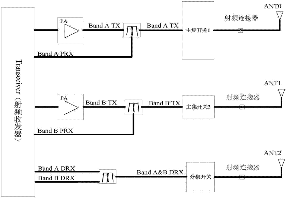
[0077] refer to Figure 7 , shows a schematic structural diagram of a radio frequency front-end device according to Embodiment 3 of the present invention.

[0078] The radio frequency front-end device of the embodiment of the present invention implements CA between uplink and downlink bands based on FDD frequency division mode. Since FDD is a frequency division mode of operation, TX and RX are performed simultaneously. In the embodiment of the present invention, a quadruplexer is used to configure the switch port of an antenna to realize simultaneous transmission and reception of signals in two frequency bands, and the other antenna realizes signal transmission in two frequency bands. Auxiliary reception, in order to achieve the purpose of two antennas supporting uplink and downlink CA between two FDD frequency bands.

[0079] The radio frequency front-end device of the embodiment of the present invention includes: a third radio frequency transceiver 301, a fifth PA 302, a si...


PUM


Abstract

The invention provides a radio frequency front end device. According to the radio frequency front end device, a first band signal transmitter pin of a first radio frequency transceiver, a first PA (Power Amplifier), a first bandpass filter and a first end of a first switch are connected in sequence. A first band primary signal receiver pin, a second band diversity signal receiver pin and a first double-filter are connected. The first double-filter is connected with a second end of the first switch. The control end of the first switch, a first radio frequency connector and a first antenna are connected in sequence. A second band signal transmitter pin, a second PA, a second bandpass filter and a first end of a second switch are connected in sequence. A second band primary signal receiver pin, a first band diversity signal receiver pin and a second double-filter are connected. The second double-filter is connected with a second end of the second switch. The control end of the second switch, a second radio frequency connector and a second antenna are connected in sequence. According to the radio frequency front end device, a layout area of a PCB and design complexity can be reduced.

Description

technical field [0001] The invention relates to the technical field of communications, in particular to a radio frequency front-end device. Background technique [0002] With the rapid development of global LTE networks, more and more countries are developing LTE services. However, due to the large number of LTE frequency bands, some operators allocate narrow frequency bands, so CA (Carrier Aggregation, Carrier Aggregation) technology came into being. In order to integrate the fragmented spectrum and increase the rate of data services. [0003] According to the frequency band, CA can be divided into two types: intra-band CA and inter-band CA; according to the sending and receiving mode, it can be divided into uplink CA and downlink CA. For example, 2UL CA (2-band inter-band uplink CA) refers to simultaneous transmission of two frequency bands, and 2DL CA (2-band inter-band downlink CA) refers to simultaneous reception of two frequency bands. Two-band uplink and downlink in...

Claims


Application Information

Patent Timeline
Patent Type & Authority Applications(China)
IPC IPC(8): H04B1/40H04B1/44H04B1/00
CPCH04B1/40H04B1/0057H04B1/44
Inventor 张厦詹天增
Owner VIVO MOBILE COMM CO LTD
Why Eureka
Try Eureka