
Powder mixing device and powder mixing method

A mixing device and powder technology, applied in mixers, fluid mixers, chemical instruments and methods, etc., can solve problems such as affecting the quality of laser cladding, large fluctuations in powder feeding rate, affecting work efficiency, etc., to save resources , the effect of increasing the mixing quality and improving the cladding quality

Active Publication Date: 2017-07-07
NANJING HUIRUI PHOTOELECTRIC TECH CO LTD
View PDF4 Cites 13 Cited by
  • Summary
  • Abstract
  • Description
  • Claims
  • Application Information

AI Technical Summary

Problems solved by technology

[0004] In the above-mentioned prior art, it is necessary to use special equipment for powder mixing operation, which requires a certain amount of preparation time and manpower, especially when long-term continuous laser cladding operations are required, which will significantly affect work efficiency; and different powders usually have Different densities will naturally separate during mechanical mixing. Those with high density will deposit downward and those with low density will rise upward, so the mixing uniformity is poor; after the powder is pre-prepared, if you want to modify the proportion, you must increase it. The powder is re-prepared and cannot be adjusted during the laser cladding operation; due to the simplicity of the multi-way connector, turbulence is prone to occur when the multi-channel air flow converges, which leads to large fluctuations in the powder feeding rate, which ultimately affects the quality of laser cladding

Method used


Image

  • Powder mixing device and powder mixing method
  • Powder mixing device and powder mixing method
  • Powder mixing device and powder mixing method

Examples


Embodiment Construction

[0029] The specific implementation manner of the present invention will be described in more detail below with reference to schematic diagrams.

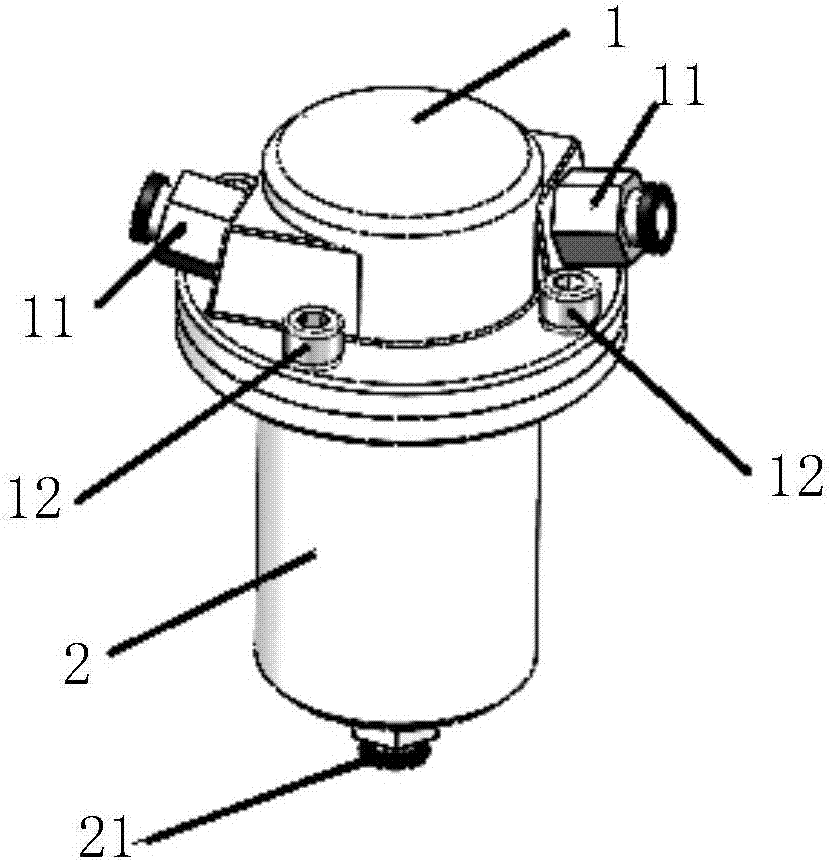
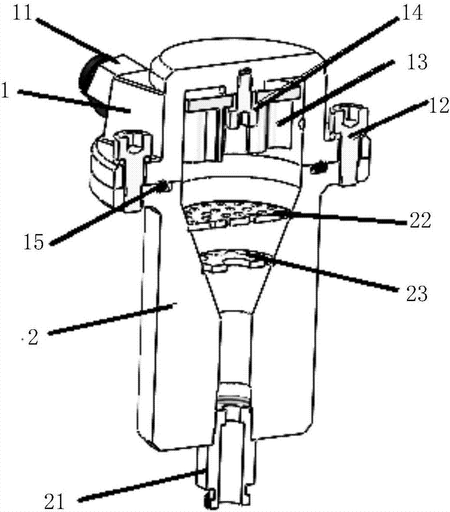
[0030] The present invention proposes a powder mixing device and method for mixing multiple powders to be mixed, wherein the powder mixing device includes: a cover and a detachably connected body, such as figure 1 As shown, specifically, the cover and the body are connected through detachable components, and further, are detachably connected through fastening screws and gaskets 12. The present invention does not impose any restrictions on the detachable connection parts of the cover 1 and the body 2 . In order to increase the sealing performance of the inner cavity of the cover body 1 and the body 2, the powder mixing device in this embodiment also includes a sealing ring 15, and the present invention does not impose any restrictions on its material quantity, material and shape.

[0031] When the powder-carrying airflow of multiple ...


PUM


Abstract

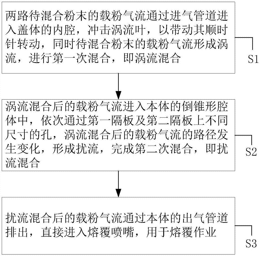
The invention provides a powder mixing device and a powder mixing method. Multiple paths of to-be-mixed powder carrying airflows respectively enter into an inner chamber of a cover through a plurality of air inlet pipes arranged on the cover, and meanwhile, a vortex blade in the inner chamber of the cover is driven to rotate, namely, a powder-carrying airflow direct mixing manner is adopted for mixing the to-be-mixed powder. Specifically, the vortex blade is used for mixing, the use of multiple connectors is avoided and the possibility of turbulence in the gathering process of multiple paths of airflows is reduced, so that the mixing quality is promoted; the powder-carrying airflows respectively enter into the air inlet pipes so as to complete the mixing of the powder in the powder mixing device, so that the time and labor for manually mixing can be saved, the resource can be saved and the cost can be lowered; the powder mixing device can be mounted at a fusion covering end, the uniformly mixed powder can be directly connected with a fusion covering nozzle through an air outlet pipeline and the laser fusion covering is performed, so that the worse uniformity caused by various unstable factors in the process of conveying after mixing can be avoided and the fusion covering quality is promoted.

Description

technical field [0001] The invention relates to the field of laser cladding, in particular to a powder mixing device and method. Background technique [0002] In the field of laser cladding, it is necessary to use a special powder delivery device (or powder feeder for short) to provide metal or non-metal powder to the cladding nozzle. The powder feeder can deliver single or multi-channel powder, generally speaking, each powder channel only provides one kind of powder. However, laser cladding often requires the use of mixed powders, that is, powders that are uniformly mixed in a certain volume or mass ratio of two or more different materials and powders of different properties. [0003] At present, the main preparation method of mixed powder is mechanical mixing in advance, that is, various powders that need to be mixed are mixed evenly in advance according to a certain ratio, and then transported to the cladding nozzle through a pipeline through a powder feeder. It is also...

Claims


Application Information

Patent Timeline
Patent Type & Authority Applications(China)
IPC IPC(8): B01F13/10B01F5/00C23C24/10
CPCC23C24/10B01F25/103B01F25/4233B01F33/805B01F33/822
Inventor 黄斌彧袁融刘文蔡国双
Owner NANJING HUIRUI PHOTOELECTRIC TECH CO LTD
Learn More