
Suspension mechanism provided with hub motor

A hub motor and suspension technology, which is applied in the direction of suspension, elastic suspension, steering mechanism, etc., can solve the problems of poor vehicle handling performance, tight wheel arrangement of suspension structure, etc., and achieve compact arrangement of wheel edges, ensure strength and Rigidity, the effect of ensuring handling stability

Pending Publication Date: 2017-07-07
CHINA FIRST AUTOMOBILE
View PDF4 Cites 7 Cited by
  • Summary
  • Abstract
  • Description
  • Claims
  • Application Information

AI Technical Summary

Problems solved by technology

[0004] The present invention provides an optimally arranged suspension structure equipped with a hub motor in order to solve the problem that the wheels of the existing suspension structure equipped with the hub motor are tensely arranged, resulting in poor vehicle maneuverability

Method used


Image

  • Suspension mechanism provided with hub motor
  • Suspension mechanism provided with hub motor
  • Suspension mechanism provided with hub motor

Examples


Embodiment Construction

[0014] The structure of the present invention will be described in further detail below in conjunction with the embodiments given in the accompanying drawings.

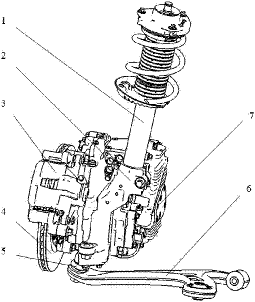
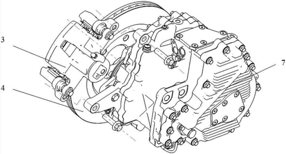
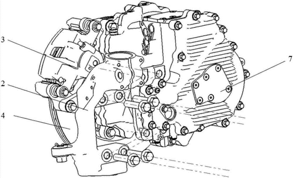
[0015] refer to Figures 1 to 5 , a suspension structure equipped with a hub motor, including a strut 1, a steering knuckle 2, a brake caliper 3, a brake disc 4, a ball joint assembly 5, a control arm 6 and a hub motor 7; the brake caliper 3 is threaded Fixedly connected to the shell of the hub motor 7, the brake disc 4 is set on the bearing unit of the hub motor 7, and the steering knuckle 2 is used as a wheel side bracket in a C-shape. The body is fastened by bolts; the upper end of the steering knuckle 2 is clamped to the sliding column 1 through bolts, and the lower end is fixedly connected with the shell of the ball joint assembly 5 through three-point internal threads, and the ball stud pin of the ball joint assembly 5 passes through the taper surface. It is interference fit with the control arm 6, and the thre...


PUM


Abstract

The invention relates to the technical field of electric vehicles, in particular to a suspension mechanism provided with a hub motor. The suspension mechanism comprises a slide column, a steering knuckle, a brake caliper, a brake disc, a ball assembly, a control arm and the hub motor. The brake caliper is fixed connected to a shell of the hub motor through a thread. The brake disc is arranged on a bearing unit of the hub motor. The steering knuckle is used as a wheel edge bracket, is of a C shape and is fastened to the shell of the hub motor through four inner threaded holes in the middle of the steering knuckle and bolts. The upper end of the steering knuckle is clamped to the slide column through a bolt, and the lower end of the steering knuckle is fixedly connected a shell of the ball assembly through a three-point internal thread. A ball pin of the ball assembly is in interference fit with the control arm through a conical surface. The threaded part in the ball pin is fastened to the control arm through a nut. By adoption of the suspension mechanism, the problem that the wheel edge arrangement space is tight is solved, strength and rigidity of the shell of the hub motor can be ensured, the effect that the ball assembly is arranged close to the central face of a tire can be achieved, and by setting reasonable master pin geometrical parameters, the control stability of a vehicle can be ensured.

Description

technical field [0001] The invention relates to the technical field of electric vehicles, in particular to a suspension structure applied to a hub motor. Background technique [0002] The problem of environmental pollution is serious, and traditional vehicle exhaust is one of the main sources of pollution. Electric vehicles driven by in-wheel motors use clean energy and help alleviate environmental pollution problems. Wheel hub motors mainly include parallel shaft type and direct drive type. This patent mainly solves the problem of suspension layout of electric vehicles driven by parallel shaft type hub motors. [0003] For electric vehicles driven by parallel shaft hub motors, the shaft hub motors are usually arranged eccentrically with respect to the wheel center, which takes up a lot of space around the wheel. Usually, the control arm and strut assembly are arranged on the motor housing and shortened The control arm method solves the problem of tight space for the arran...

Claims


Application Information

Patent Timeline
Patent Type & Authority Applications(China)
IPC IPC(8): B60G3/02B60K7/00B62D7/18
CPCB62D7/18B60G3/02B60K7/0007B60K2007/0038B60K2007/0061B60G3/06B60G2200/1424B60G2300/50B60G2204/148B60G2204/416B60G2200/142
Inventor 王微陈磊王仕伟陈志刚侯杰彭大祥潘迪
Owner CHINA FIRST AUTOMOBILE
Learn More