
Construction method of suspended steel gallery

A construction method and hanging technology, which is applied in the field of hoisting construction of hanging steel corridors, can solve problems such as the internal stress of the hanging structure deformation, the stress state does not match the design, and the inability to complete the bearing corridors, etc., to avoid The effect of reinforcement, shortening the construction period, and accelerating construction efficiency

Active Publication Date: 2017-07-07
CHINA CONSTR SECOND ENG BUREAU LTD +1
View PDF2 Cites 11 Cited by
  • Summary
  • Abstract
  • Description
  • Claims
  • Application Information

AI Technical Summary

Problems solved by technology

[0004] The problems existing in the existing construction are: First, the hanging structure of the steel corridor is assembled first, and then the truss structure is assembled upwards. The stress state does not match the design, and the lower hanging structure is likely to cause huge deformation and internal stress.
Second: The top surface of the structure below the corridor, such as the basement roof, has far insufficient bearing capacity. The basement roof should be reinforced, such as using steel, scaffolding to support the roof, or adding steel columns and steel frames to the basement structure. Beams are used to enhance the bearing capacity of the basement roof, which consumes a lot of materials and time, and increases the construction cost; when the weight of the steel corridor of some projects is too heavy, the task of carrying the corridor cannot be completed by reinforcing the basement roof
Third: The number of tower cranes is limited and covers a large area. Using tower cranes for assembly is slow and tower cranes cannot meet other professional construction

Method used


Image

  • Construction method of suspended steel gallery
  • Construction method of suspended steel gallery
  • Construction method of suspended steel gallery

Examples


Embodiment Construction

[0045]The present invention is further described below in conjunction with accompanying drawing and embodiment:

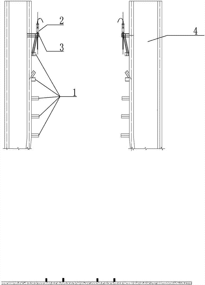
[0046] The present invention is a hoisting construction method for a hanging steel corridor. The hanging steel corridor is connected between the main structures 4 that have been built. Step 1 is to install a pre-installed rod 1 at the design elevation of the steel corridor , set lifting platforms 3 on the pre-installed rods 1, set at least four sets of lifting platforms 3, and install a hydraulic lifter 2 on each set of lifting platforms 3 (such as figure 1 shown); install hydraulic synchronous lifting system equipment, including hydraulic pump source system, hydraulic lifter 2, sensors, etc.;

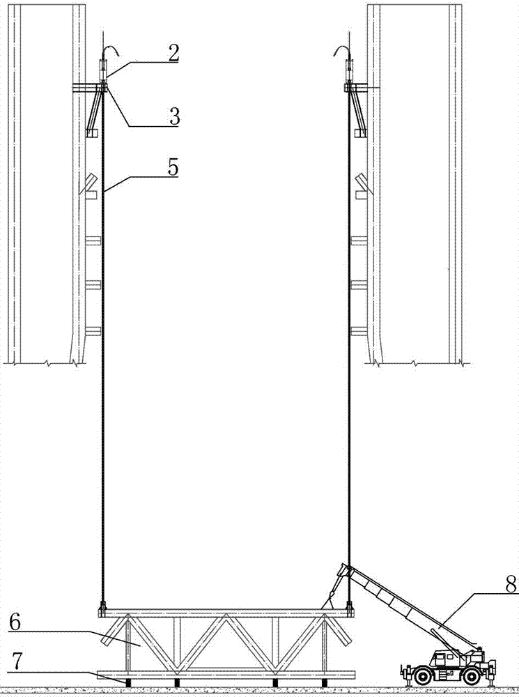
[0047] Step 2, assemble under the projection of the predetermined installation position of the suspended steel corridor, use the truck crane 8 to assemble the upper truss structure 6 of the suspended steel corridor at the elevation of ±0.000 of the basement roof, and debug ...


PUM


Abstract

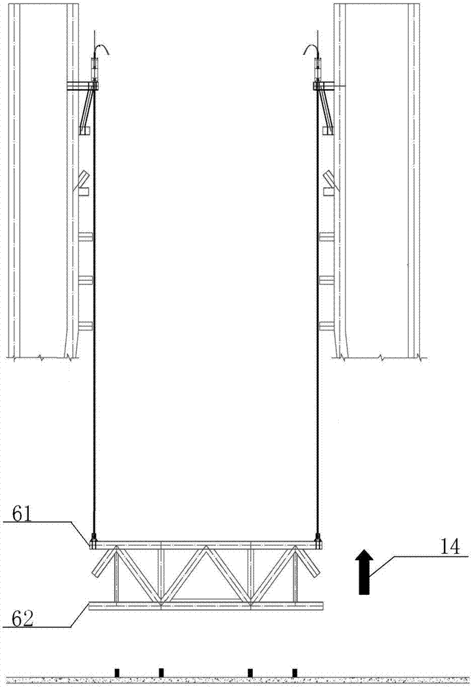
The invention discloses a construction method of a suspended steel gallery. The suspended steel gallery is connected between main body structures; a preassembled bar is firstly arranged at designed elevation of the suspended steel gallery, a lifting platform is arranged, and meanwhile, a hydraulic lifter is arranged; an upper truss structure of the suspended steel gallery is spliced on the ground, the hydraulic lifter is debugged to lift in a segmented manner, wherein the lifting height of each time is the height of one layer of suspended structure; and the suspended steel gallery is lifted to the elevation for welding after assembly is completed. According to the method, one-time overall lifting method of the multi-layer suspended steel gallery is changed into a hydraulic multi-time segmented lifting method, so that large-range reinforcement of a basement roof is avoided, the construction period is shortened, the cost is reduced, the designed mechanical principle is matched and stress deformation and internal stress generation of a suspended structure are avoided. The appearance quality of the steel gallery and the quality of a welding line and a member meet the national current acceptance standard requirements; and the design idea is achieved.

Description

technical field [0001] The invention relates to the technical field of building steel structure installation and construction, in particular to a hoisting construction method for a suspended steel corridor. Background technique [0002] With the increasing shortage of urban construction land, people's pursuit of architectural art and the sharp increase of construction costs, there will be more and more aerial long-span heavy-duty steel corridors in super high-rise twin towers. For large-span and high-height buildings For buildings, the way of using hydraulic overall lifting is the first choice, but the steel corridors have different shapes and weights. The appropriate lifting method must take into account cost, safety and construction simplicity. [0003] The corridor is one of the complex high-rise building structural systems. It is a connecting body, which is arranged perpendicular to the horizontal direction of the building. The steel corridor structure of most urban cons...

Claims


Application Information

Patent Timeline
IPC IPC(8): E04G21/14
CPCE04G21/14
Inventor 刘培苏铠张益民雷志强程志军朱早孙
Owner CHINA CONSTR SECOND ENG BUREAU LTD
Learn More