
Gas automatic ignition control method and device

A gas device and automatic ignition technology, applied in heating fuel, gaseous heating fuel, household heating, etc., can solve problems such as explosion and increased gas concentration

Active Publication Date: 2017-07-07
GREE ELECTRIC APPLIANCES INC
View PDF4 Cites 10 Cited by
  • Summary
  • Abstract
  • Description
  • Claims
  • Application Information

AI Technical Summary

Problems solved by technology

[0005] In view of this, the purpose of the present invention is to provide a gas automatic ignition control method and device, which is used to solve the problem that the increase of gas concentration may cause explosion after the gas device fails to ignite for many times

Method used


Image

  • Gas automatic ignition control method and device
  • Gas automatic ignition control method and device
  • Gas automatic ignition control method and device

Examples


Embodiment Construction

[0066] The following will clearly and completely describe the technical solutions in the embodiments of the present invention with reference to the accompanying drawings in the embodiments of the present invention. Obviously, the described embodiments are only some, not all, embodiments of the present invention. Based on the embodiments of the present invention, all other embodiments obtained by persons of ordinary skill in the art without making creative efforts belong to the protection scope of the present invention.

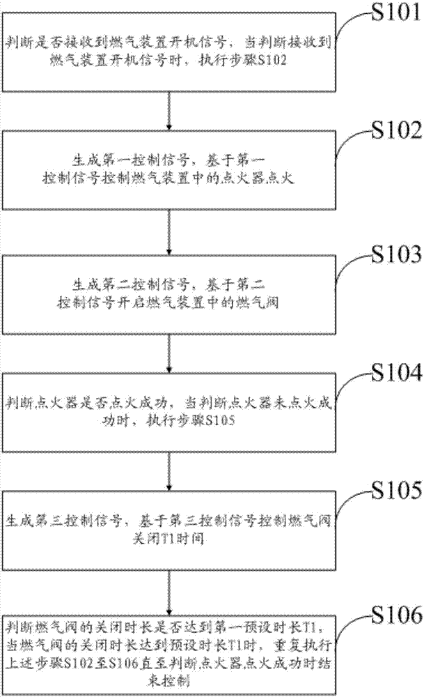
[0067] like figure 1 As shown, it is a flow chart of Embodiment 1 of a gas automatic ignition control method disclosed in the present invention, which is applied to a gas device, and the method includes the following steps:

[0068] S101. Judging whether the start-up signal of the gas device is received, and when it is judged that the start-up signal of the gas device is received, step S102 is executed;

[0069] When it is necessary to ignite, first make sure...


PUM


Abstract

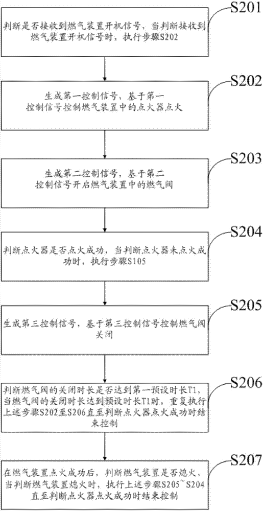
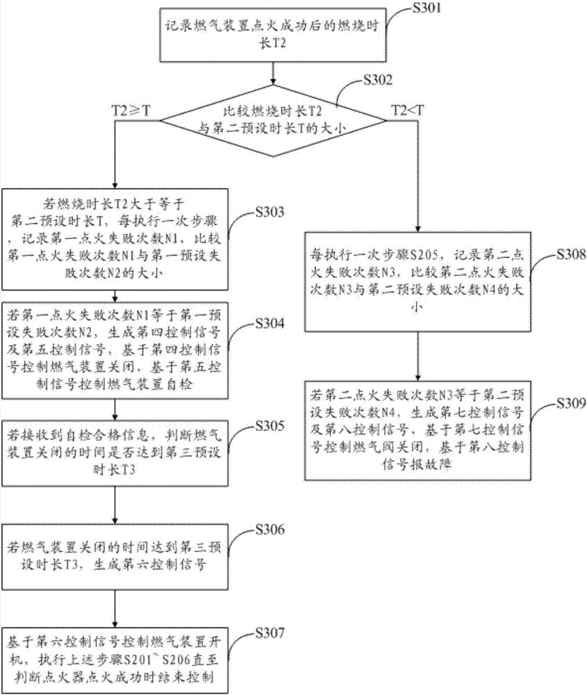
The invention provides a gas automatic ignition control method which comprises the following steps: judging whether a gas equipment start-up signal is received or not; when judging that the gas equipment start-up signal is received, generating a first control signal, and controlling an ignitor in gas equipment to light a fire based on the first control signal; generating a second control signal, and opening a gas valve in the gas equipment based on the second control signal; judging whether the ignitor starts burning successfully or not; when judging that the ignitor does not light a fire successfully, generating a third control signal, and controlling the gas valve to be closed for a first preset time T1 based on the third control signal; and judging whether the closing time of the gas valve reaches the first preset time T1 or not, and repeating the above fire-lighting steps till a fire is lighted successfully when the closing time of the gas valve reaches the first preset time T1. According to the gas automatic ignition control method, the gas valve is closed for a certain time after the ignitor fails to light a fire. Therefore, gas which is not fully burned can escape, and the problem that an explosion is possibly caused by an increase in the gas concentration can be solved.

Description

technical field [0001] The invention relates to the technical field of gas devices, and more specifically, to a method and device for controlling automatic ignition of gas. Background technique [0002] Generally speaking, gas devices refer to all appliances that use gas (artificial gas, liquefied petroleum gas, natural gas) as fuel, such as gas water heaters and wall-hung boilers used in our daily life and industry. [0003] During the use of gas appliances, flameout or ignition failure often occurs. In the prior art, when the flameout or ignition failure occurs, the gas device will automatically ignite immediately to resume gas combustion. Under normal circumstances, this treatment method can greatly reduce the heat supply stop caused by abnormal flameout. [0004] In some special cases, if there are multiple ignition failures and the gas is not fully burned, the gas concentration in the gas device will become higher and higher, eventually leading to an explosion. Conte...

Claims


Application Information

Patent Timeline
IPC IPC(8): F24H9/20F24C3/12
CPCF24C3/126F24H9/2035
Inventor 邹宏亮左攀吴凤娇张晓慈夏海石
Owner GREE ELECTRIC APPLIANCES INC
Learn More