
Smart ammeter terminal-based smart home control system and method

A smart home control, smart meter technology, applied in general control systems, control/regulation systems, electrical program control, etc., can solve the problem that the metering, billing, management and control functions cannot meet the requirements, and do not have smart home control functions. , the number and types of equipment, etc., to achieve the effect of improving management efficiency and reliability, improving safety and reliability, and improving security

Inactive Publication Date: 2017-07-07
STATE GRID SHANDONG ELECTRIC POWER
View PDF7 Cites 4 Cited by
  • Summary
  • Abstract
  • Description
  • Claims
  • Application Information

AI Technical Summary

Problems solved by technology

With the increase of user types and the diversification of application scenarios, the metering, billing, management and control functions of existing electric meters cannot meet the requirements, and solutions that meet the needs of multiple users and multiple scenarios must be proposed;
[0005] (2) Does not have smart home control function
The current smart home control functions are mostly based on the Internet. The control objects are generally the corresponding power switches of the home. There are many problems in the number of control objects, the number and types of equipment involved, and the control mode is relatively inferior.

Method used


Image

  • Smart ammeter terminal-based smart home control system and method
  • Smart ammeter terminal-based smart home control system and method

Examples


Embodiment Construction

[0043] Below in conjunction with accompanying drawing and embodiment the present invention will be further described:

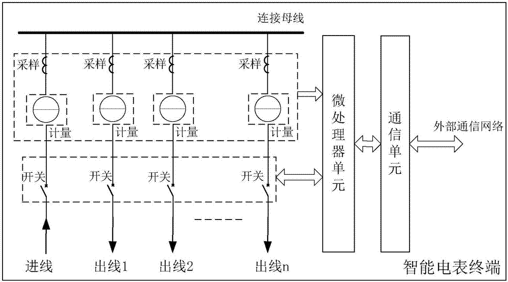
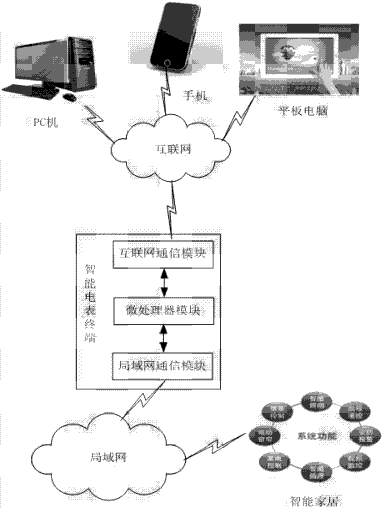
[0044] figure 2 It is the smart home control system based on the smart meter terminal of the present invention. Such as figure 2The smart home control system based on the smart meter terminal of the present invention shown in the present invention includes a smart meter terminal, and the smart meter terminal is also respectively connected with the smart home of the corresponding user and the user terminal; the microprocessor is used for Receive the control command of the user terminal and forward it to the smart home of the corresponding user, and the smart home responds to the control command and executes the corresponding action.

[0045] Such as figure 1 As shown, the smart meter terminal includes a microprocessor control unit, a communication unit, a wiring bus, an incoming line and multiple outgoing lines, and each outgoing line corresponds to a use...


PUM


Abstract

The present invention discloses an smart ammeter terminal-based smart home control system and a method. The smart ammeter terminal-based smart home control system comprises an smart ammeter terminal. The smart ammeter terminal comprises a wiring bus, an incoming line and a plurality of outgoing lines. Each outgoing line is corresponding to one user. The incoming line is connected with the wiring bus through an electric energy total measurement module. Each outgoing line is connected with the wiring bus through a sub-switch, an electric energy measurement sub-module and a voltage and current instantaneous value sampling sub-module. The electric energy measurement sub-module comprises a microprocessor and an electric energy measurement chip, wherein the microprocessor and the electric energy measurement chip are in mutual communication with each other. The microprocessor is also respectively connected with the smart home of a corresponding user and a user terminal. The microprocessor is used for receiving a control command from the user terminal and forwarding the control command to the smart home of the corresponding user. The smart home performs a corresponding action in response to the control command.

Description

technical field [0001] The invention relates to the field of smart meters, in particular to a smart home control system and method based on a smart meter terminal. Background technique [0002] A smart meter is an intelligent terminal of a smart grid. It is no longer an electric energy meter in the traditional sense. In addition to the basic electricity consumption measurement function of a traditional electric energy meter, a smart electric meter is designed to meet the development needs of the smart grid and connect a large number of distributed clean energy generation It should also have accurate two-way multi-rate metering function, user-side control function, two-way data communication function of multiple data transmission modes, support for multi-user and multi-scenario use, support for electricity price curve release and time-of-use electricity price Intelligent functions such as billing, real-time collection and transmission of voltage and current data, and value-ad...

Claims


Application Information

Patent Timeline
Patent Type & Authority Applications(China)
IPC IPC(8): G05B19/418G05B15/02
CPCY02P90/02G05B19/418G05B15/02G05B2219/2642
Inventor 崔其会张映晖董罡石岩张晓华李建鹏李作兵李卫胜
Owner STATE GRID SHANDONG ELECTRIC POWER
Learn More