
UAV real-time obstacle avoidance system and method based on binocular vision

A technology of binocular vision and unmanned aerial vehicles, which is applied in control/regulation systems, non-electric variable control, instruments, etc., can solve problems such as easy lag, low precision, and loss of user groups, so as to ensure safe flight, The system structure is simple and the effect of avoiding hysteresis

Inactive Publication Date: 2017-07-07
湖南基石信息技术有限公司
View PDF0 Cites 24 Cited by
  • Summary
  • Abstract
  • Description
  • Claims
  • Application Information

AI Technical Summary

Problems solved by technology

But in most cases, before the unmanned aerial vehicle takes off, its flight environment is unknown, and obstacle information can only be obtained through real-time online detection during the execution of the flight mission, so it is very likely to encounter obstacles during the flight Obstacles cannot be detected and avoided in time, resulting in the collision of the drone with the obstacle and the bombing of the aircraft, which brings great losses to the user group
[0003] In response to the above problems, scholars have devoted their energy to how to make UAVs autonomously avoid obstacles. A few UAV companies have applied infrared, ultrasonic and other sensors as distance sensors to UAV obstacle avoidance. However, using the above sensors for obstacle inspection has problems such as limited detection distance, low accuracy, and prone to false detection and missed detection.
In addition, there is another UAV obstacle avoidance method that implements the obstacle avoidance function on the ground station, transmits the image to the ground segment through image transmission, performs a series of obstacle avoidance algorithm processing, and then transmits the planned best The optimal path returns to the flight control terminal for control. On the one hand, this method is prone to hysteresis, and on the other hand, it relies too much on the stability of the wireless link. Once there is a problem in the process of image transmission and data transmission, it will directly affect obstacle avoidance. system

Method used


Image

  • UAV real-time obstacle avoidance system and method based on binocular vision
  • UAV real-time obstacle avoidance system and method based on binocular vision
  • UAV real-time obstacle avoidance system and method based on binocular vision

Examples


Embodiment Construction

[0027] The present invention will be further described in detail below in conjunction with the embodiments and the accompanying drawings, but the embodiments of the present invention are not limited thereto.

[0028] At present, the fast obstacle avoidance of UAV is an important problem in the field of UAV research, and it has many characteristics different from the obstacle avoidance of land intelligent robots. The flying environment of UAVs is uncertain and complex, and it is necessary to continuously detect and measure the surrounding environment to avoid collisions with obstacles or even crashes. UAVs are small in size and limited in load capacity, and cannot carry heavy acoustic detectors. Therefore, it is necessary to find a real-time obstacle avoidance system and method for UAVs based on binocular vision.

[0029] The present invention provides a real-time obstacle avoidance system for unmanned aerial vehicles based on binocular vision, such as figure 1 As shown, the s...


PUM


Abstract

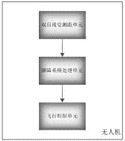
The invention provides a UAV real-time obstacle avoidance system based on binocular vision. The UAV real-time obstacle avoidance system comprises a binocular vision ranging unit, an obstacle avoidance system processing unit and a flight control unit. The binocular vision ranging unit is based on a parallax principle, obtains two images of an obstacle by utilizing difference of positions of a left camera and a right camera, calculating positional deviation between corresponding points of the images to obtain obvious depth perception, establishing correspondence between features, and corresponding a same space physical point to mapping points in the different images, so as to obtain three-dimensional information of the obstacle. The obstacle avoidance system processing unit is responsible for performing omnidirectional obstacle detection, and planning an optimal flight path which is capable of avoiding the obstacle to the flight control unit. The flight control unit is responsible for executing instructions of the obstacle avoidance system processing unit, so that a UAV performs autonomous obstacle avoidance along the planned path. The UAV real-time obstacle avoidance system and the UAV real-time obstacle avoidance method can guarantee the safe flight of the unmanned aerial vehicle.

Description

technical field [0001] The invention relates to the field of UAV flight control, in particular to a real-time obstacle avoidance system and method for UAVs based on binocular vision. Background technique [0002] At present, countries have invested a lot of human, material and financial resources in the research and development of ground robots, and have achieved fruitful results in the path planning of the ground and its people. However, in recent years, with the continuous development of science and technology, more and more people use drones for entertainment, aerial photography, commercial use, agricultural use, rescue, etc. But in most cases, before the unmanned aerial vehicle takes off, its flight environment is unknown, and obstacle information can only be obtained through real-time online detection during the execution of the flight mission, so it is very likely to encounter obstacles during the flight Obstacles cannot be detected and avoided in time, resulting in t...

Claims


Application Information

Patent Timeline
Patent Type & Authority Applications(China)
IPC IPC(8): G05D1/10
CPCG05D1/101
Inventor 张长隆王苗苗
Owner 湖南基石信息技术有限公司
Learn More