Eureka AIR delivers breakthrough ideas for toughest innovation challenges, trusted by R&D personnel around the world.

Plasma processor with temperature measuring device

A technology of temperature measurement and plasma, applied in discharge tubes, electrical components, circuits, etc., can solve problems such as unevenness, actual temperature distortion, and small contact area

Active Publication Date: 2017-07-07
ADVANCED MICRO FAB EQUIP INC CHINA
View PDF5 Cites 5 Cited by
  • Summary
  • Abstract
  • Description
  • Claims
  • Application Information

AI Technical Summary

Problems solved by technology

At the same time, the shell of the thermocouple is made of stainless steel, and the front end is often circular. Due to the existence of processing tolerances and surface roughness of the contact surface, the actual effective contact area is small and uneven.
Therefore, the temperature actually measured by the thermocouple is distorted.
At the same time, because a large amount of radio frequency power is coupled between the upper and lower electrodes, and the thermocouple is made of conductive material, a large amount of radio frequency energy will form a large current through the thermocouple as a grounding path, which will not only cause the external controller to fail to follow the electrical signal Judging the temperature, and the high heat generated by the large current itself will also distort the actual temperature

Method used


Image

  • Plasma processor with temperature measuring device
  • Plasma processor with temperature measuring device
  • Plasma processor with temperature measuring device

Examples


Embodiment Construction

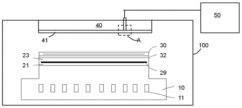
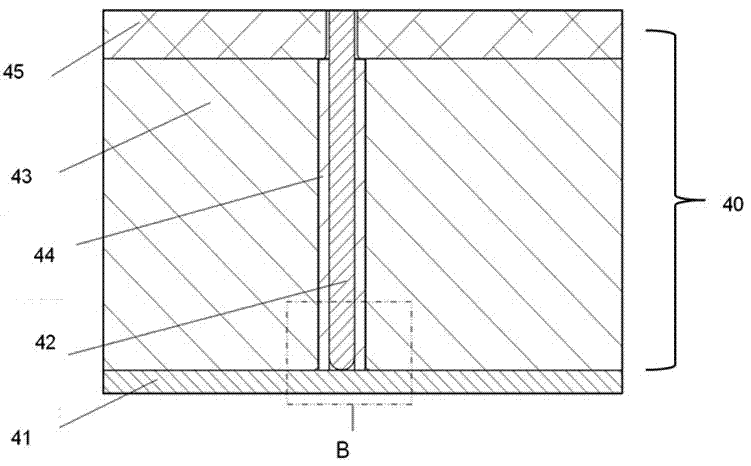
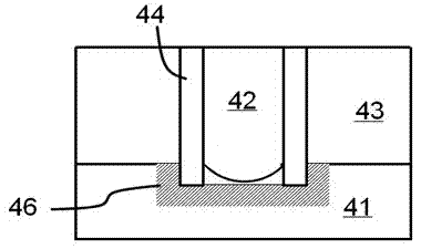
[0012] Such as figure 2 Shown is a schematic diagram of the thermocouple installation structure in the plasma processing device of the present invention, figure 2 for figure 1 The enlarged structural diagram at A in the middle to clearly show the structural features. In the present invention, the upper surface of the gas shower head 41 includes a heating plate 43, and the heating plate includes an aluminum diffuser plate and a heating element such as a resistance wire (not shown in the figure) embedded therein. An installation plate 45 is also included above the heating plate 43 for installing and fixing the thermocouple 42 and the gas shower head 41 on the heating plate 43 below. The thermocouple 42 of the present invention includes a shell usually made of stainless steel, and inside the shell are at least two metal wires made of different materials, and the two metal wires will generate different potential differences with different temperatures. In particular, the pres...


PUM


Abstract

The invention discloses a plasma processor, which comprises a reaction cavity. A base is located at the inner lower part of the reaction cavity for fixing a substrate; a radio frequency power supply is connected onto the lower electrode inside the base; a gas spraying head is located at the top part of the reaction cavity; the reaction cavity is internally provided with at least one component ready for temperature measurement; the component ready for temperature measurement comprises a first surface facing the substrate above the base and a second surface located on the back surface of the first surface; a heating plate and the second surface of the component ready for temperature measurement are mutually fastened at the component ready for temperature measurement; the heating plate comprises a through hole, the through hole is internally provided with a thermal couple and an elastic insulation material coating the outer surface of the thermal couple, the thermal couple comprises a first end and the first end and the second surface of the component ready for temperature measurement form a first contact area, the elastic insulation material also comprises a first end and the first end and the second surface of the component ready for temperature measurement form an annular contact area, and the annular contact area surrounds the first contact area.

Description

technical field [0001] The invention relates to the technical field of semiconductor manufacturing, in particular to a temperature control device for a plasma processor. Background technique [0002] Such as figure 1 As shown, the conventional plasma processing device includes a reaction chamber 100 , the reaction chamber 100 includes a base 10 , the base includes a lower electrode and the lower electrode is connected to a radio frequency power supply, and the base 10 also includes a cooling liquid channel 11 . A heater is included above the base, and the heater includes two upper and lower layers of insulating material layers 21, 23, and a heating element such as a resistance wire 29 located between the two layers of insulating material layers. An electrostatic chuck 30 is fixed on the upper surface of the heater through silica gel 32 , and the wafer to be processed is fixed on the electrostatic chuck 30 during processing. Opposite to the base in the reaction chamber is a...

Claims


Application Information

Patent Timeline
Patent Type & Authority Applications(China)
IPC IPC(8): H01J37/32
CPCH01J37/32798
Inventor 徐朝阳周旭升陈妙娟
Owner ADVANCED MICRO FAB EQUIP INC CHINA
Why Eureka
Eureka Blog
Learn More