Motor protection circuit and method of controlling the motor protection circuit

A motor protection circuit and protection resistor technology, applied in emergency protection circuit devices, electrical components, etc., can solve problems such as bulkiness, damage to fuses or transient voltage suppressor control circuits, and achieve high integration, low cost, and practicality. strong effect

Inactive Publication Date: 2017-07-07
SHEN ZHEN KUANG CHI HEZHONG TECH LTD
View PDF1 Cites 5 Cited by
  • Summary
  • Abstract
  • Description
  • Claims
  • Application Information

AI Technical Summary

Problems solved by technology

[0003] Aiming at the technical problem that the power supply protection circuit in the prior art relies on bulky inductors, capacitors, fuses or transient voltage sup

Method used


Image

  • Motor protection circuit and method of controlling the motor protection circuit
  • Motor protection circuit and method of controlling the motor protection circuit
  • Motor protection circuit and method of controlling the motor protection circuit

Examples


Embodiment 1

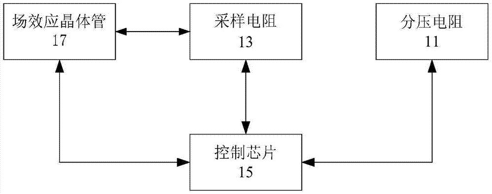
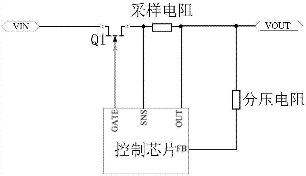
[0016] According to an embodiment of the present invention, an embodiment of a motor protection circuit is provided, figure 1 is a schematic diagram of a motor protection circuit according to an embodiment of the present invention, such as figure 1 As shown, the motor protection circuit: a voltage dividing resistor 11 , a sampling resistor 13 , a control chip 15 and a field effect transistor 17 .

[0017] Among them, the control chip 15, one end of the voltage dividing resistor 11 is connected to the control chip 15, and both ends of the sampling resistor 13 are connected to the control chip 15, for detecting that the voltage value at both ends of the voltage dividing resistor is greater than the preset voltage value Next, the power supply voltage is stabilized to a preset voltage value, and / or when it is detected that the current value flowing through the sampling resistor is greater than the preset current value, a shutdown signal is sent.

[0018] Specifically, the preset ...

Embodiment 2

[0073] According to an embodiment of the present invention, an embodiment of a method for controlling a motor protection circuit is provided. It should be noted that the steps shown in the flowcharts of the accompanying drawings can be executed in a computer system such as a set of computer-executable instructions, and , although a logical order is shown in the flowcharts, in some cases the steps shown or described may be performed in an order different from that shown or described herein.

[0074] Figure 4 is a flowchart of a method for controlling a motor protection circuit according to an embodiment of the present invention, such as Figure 4 shown, combined with Figure 4 As can be seen, the method includes the following steps:

[0075] Step S102, the control chip detects the voltage value at both ends of the voltage dividing resistor connected to the control chip, and judges whether the voltage value is greater than a preset voltage value, and / or detects the current va...


PUM

PropertyMeasurementUnit
Resistanceaaaaaaaaaa

Abstract

The invention discloses a motor protection circuit and a method of controlling the motor protection circuit. The motor protection circuit comprises a voltage division resistor, a sampling resistor, a control chip and a field effect transistor, wherein one end of the voltage division resistor accesses the control chip, and two ends of the sampling resistor access the control chip, and the control chip is used for stabilizing a power supply voltage to be a preset voltage value when a voltage value of two ends of the voltage division resistor is detected to be greater than the preset voltage value, and/or emitting a shut-off signal when a value of a current flowing through the sampling resistor is detected to be greater than a preset current value; and a grid electrode of the field effect transistor accesses the control chip and a source electrode accesses one end of the sampling resistor and is connected, and the field effect transistor is used for carrying out shutoff according to the shut-off signal generated by the control chip. In the prior art, a power supply protection circuit depends on a heavy inductor, a capacitor, a fuse or a transient voltage suppressor to prevent a condition that equipment and a control circuit are damaged because a power supply voltage current is abruptly changed. By using the circuit and the method of the invention, the above technical problem is solved.

Description

technical field [0001] The invention relates to the technical field of power management, in particular to a motor protection circuit and a method for controlling the motor protection circuit. Background technique [0002] In the field of motion control, the closing or opening of the power switch will generate large surges and peaks, resulting in large transient currents and transient voltages, which may easily cause damage to the motor and control circuit or cause the motor to work abnormally. Therefore, it is necessary to design an overcurrent and overvoltage protection circuit to prevent damage to the control circuit and the motor when the current or voltage suddenly increases. [0003] Aiming at the technical problem that the power supply protection circuit in the prior art relies on bulky inductors, capacitors, fuses or transient voltage suppressors to prevent damage to equipment and control circuits caused by sudden changes in power supply voltage and current, no effect...

Claims


Application Information

Patent Timeline
IPC IPC(8): H02H7/09
CPCH02H7/09
Inventor 不公告发明人
Owner SHEN ZHEN KUANG CHI HEZHONG TECH LTD
Why Eureka
Try Eureka