Gold steel line sanding device

The technology of gold steel wire and metal wire is applied to the field of sanding device on gold steel wire, which can solve the problems of difficult control of sand loading density and uneven sand loading, and achieve the effects of simple structure, uniform sand loading and convenient use.

Active Publication Date: 2019-01-01
安徽卡尔森新材料科技有限公司
View PDF6 Cites 0 Cited by
  • Summary
  • Abstract
  • Description
  • Claims
  • Application Information

AI Technical Summary

Problems solved by technology

However, the existing sand loading device has problems such as uneven sand loading and difficult control of sand density.

Method used


Image

  • Gold steel line sanding device
  • Gold steel line sanding device
  • Gold steel line sanding device

Examples


Embodiment Construction

[0016] In order to make the technical means, creative features, goals and effects achieved by the present invention easy to understand, the present invention will be further described below in conjunction with specific illustrations.

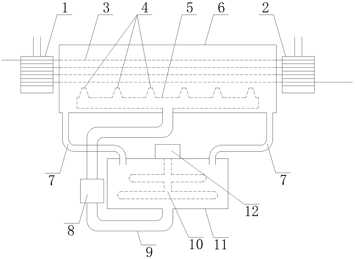
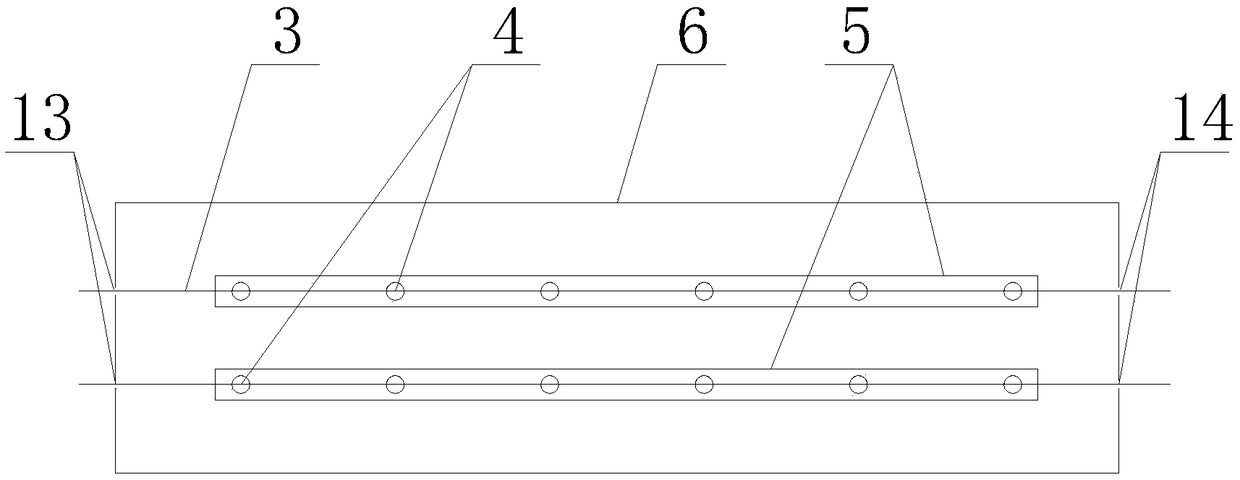
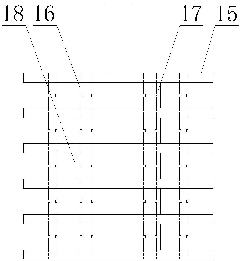
[0017] Such as Figure 1-2 As shown, a gold-steel wire sanding device includes an upper sand tank 6, the upper end of the upper sand tank 6 is open, and the incoming line conductive wheel 1, the outgoing line conductive wheel 2, the incoming line conductive wheel 1, and the outgoing line conductive wheel are respectively arranged near the two ends. 2 symmetrically arranged along the upper sand tank 6, such as image 3 , 4 As shown, the incoming line conductive wheel 1 and the outgoing line conductive wheel 2 are respectively formed by connecting spaced discs 15 through the first rotating shaft 18, and the second rotating shaft 16 is arranged at intervals along the circumferential direction near the edge of the disc 15, and the second rotating s...


PUM


Abstract

The invention discloses a diamond wire sand feeding device which comprises a sand feeding groove. A wire feeding electric conduction wheel and a wire discharging electric conduction wheel are arranged at the positions close to the two ends of the sand feeding groove correspondingly. Each of the wire feeding electric conduction wheel and the wire discharging electric conduction wheel is formed by connecting discs through a first rotating shaft, wherein the discs are distributed at intervals. Second rotating shafts are arranged at the positions, close to the edges, of the discs in the circumference direction at intervals, and grooves are formed in the positions, between every two adjacent discs, on the second rotating shafts. Metal wires are wound around the grooves. The two end faces of the sand feeding groove are provided with a pair of wire feeding grooves and a pair of wire discharging grooves parallel to the outer edges of the wire feeding electric conduction wheel and the wire discharging electric conduction wheel along the upper ends. The pair of symmetric wire feeding electric conduction wheel and wire discharging electric conduction wheel are arranged at the two ends of the sand feeding groove so that the metal wires can be wound between the two electric conduction wheels and penetrate the sand feeding groove, multiple times of sand feeding can be completed on the metal wires, the sand feeding density is flexibly controlled according to needs, and meanwhile space resources are saved; and a nozzle is located below the metal wires, sprayed chemical liquid falls back to the sand feeding groove under the gravity effect, sand feeding is more even, and the chemical liquid can be recycled.

Description

technical field [0001] The invention relates to the technical field of gold wire production, in particular to a gold wire sanding device. Background technique [0002] The gold steel wire made of electroplated diamond abrasive on the surface of the wire is a very common wire saw material used in the field of wire cutting technology. It has high cutting efficiency, small kerf, can cut multiple products at the same time, and is environmentally friendly. Many hard materials in the industry are cut with cutting steel wires or higher-quality gold steel wires, such as polysilicon slices, monocrystalline silicon, and ingots in the photovoltaic field. [0003] In the production process of gold steel wire, it needs to go through multiple processes such as wire setting, alkali cleaning, pickling, pre-plating, sanding, and reinforcement. On the surface of the wire, it plays a decisive role in the quality of the final product. However, there are deficiencies such as inhomogeneous sand...

Claims


Application Information

Patent Timeline
Patent Type & Authority Patents(China)
IPC IPC(8): C25D15/00C25D7/06
CPCC25D7/0607C25D15/00
Inventor 姜传芳周小波虞雪荣杨再明王伟刘智韬
Owner 安徽卡尔森新材料科技有限公司
Why Eureka
Try Eureka