Workpiece grinding method and polishing pad dressing method

A grinding method and technology of grinding pads, which are applied in the control of workpiece feed movement, grinding machine tools, grinding tools, etc., can solve problems such as unclear images and inability to obtain high-precision information of grinding pads, and achieve the effect of easy grinding management

Active Publication Date: 2021-03-12
FUJIKOSHI MACHINERY +1
View PDF7 Cites 0 Cited by
  • Summary
  • Abstract
  • Description
  • Claims
  • Application Information

AI Technical Summary

Problems solved by technology

[0009] However, according to Patent Document 1, since the surface properties of the grinding pad are measured during the grinding process of the workpiece, images different from actual ones or distorted due to grinding debris or grinding liquid (for example, cloudy liquid) can be formed. There is a problem that high-precision information about the surface shape of the polishing pad cannot be obtained because of unclear images

Method used


Image

  • Workpiece grinding method and polishing pad dressing method
  • Workpiece grinding method and polishing pad dressing method
  • Workpiece grinding method and polishing pad dressing method

Examples


Embodiment Construction

[0038] Hereinafter, preferred embodiments of the present invention will be described in detail based on the drawings.

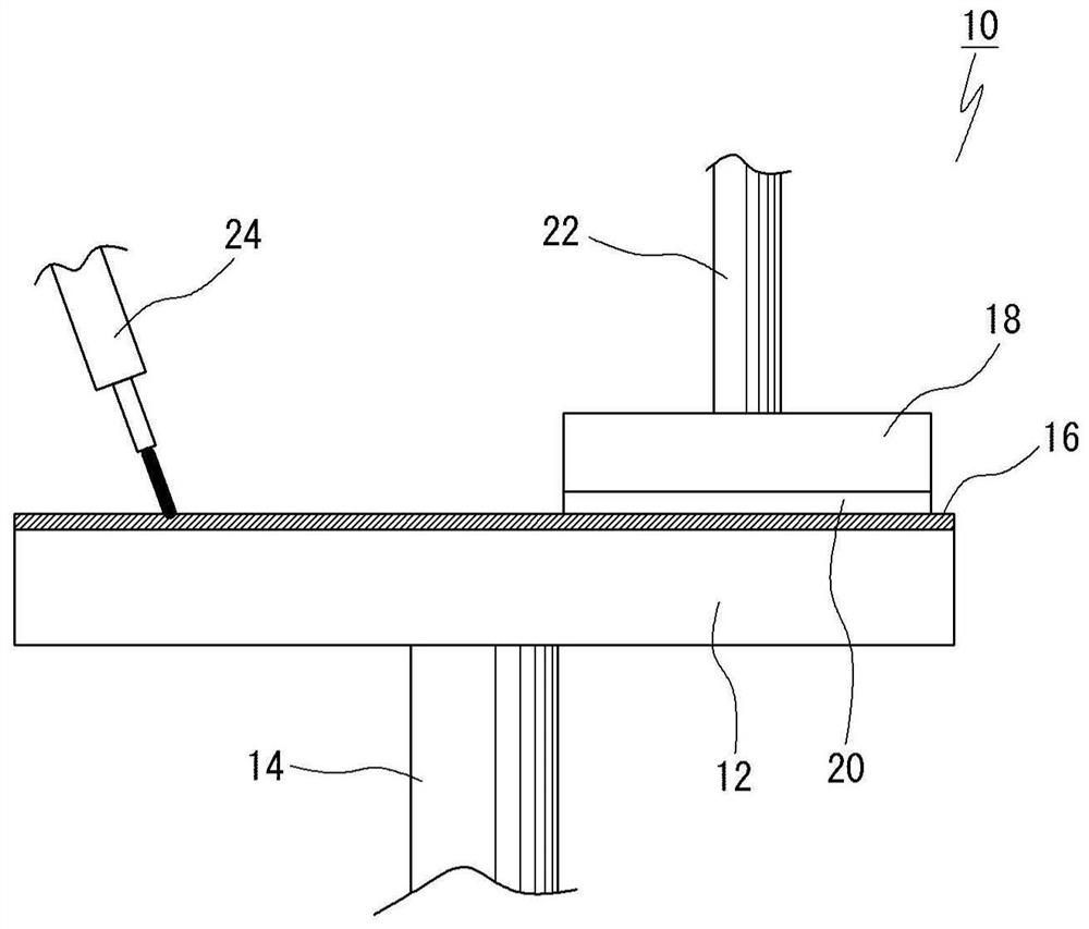
[0039] figure 1 It is an explanatory diagram showing the outline of the polishing device 10 .

[0040] Reference numeral 12 denotes a platform, which rotates in a horizontal plane around a rotating shaft 14 by a known drive mechanism (not shown). A polishing pad 16 made of, for example, foamed polyurethane as a main material is pasted on the upper surface of the platform 12 .

[0041] 18 is a grinding head, which holds a workpiece (semiconductor wafer, etc.) 20 to be ground on its lower surface side. The grinding head 18 rotates about the rotation axis 22 . In addition, the polishing head 18 can move up and down by a vertical movement mechanism (not shown) such as an air cylinder.

[0042] 24 is a slurry supply nozzle, which supplies slurry (polishing liquid) onto the polishing pad 16 .

[0043] The workpiece 20 is held on the lower surface side of the gri...


PUM


Abstract

The invention provides a workpiece grinding method and a grinding pad dressing method. This workpiece polishing method can accurately grasp the surface state of the polishing pad, and can perform high-precision dressing, thereby enabling high-precision polishing. The workpiece grinding method of the present invention is characterized in that it includes the following step: a step of obtaining correlation data in advance, wherein the correlation data represents the surface properties of the polishing pad when dressing is performed with a plurality of stages of dressing conditions, and the The respective dressing conditions of multiple stages have carried out the correlation between the grinding effect of the workpiece when the grinding pad after the dressing is used to grind the workpiece; the dressing process calculates the imaginary dressing condition that can realize the target grinding effect according to the relevant data, and uses this The estimated virtual dressing conditions are used to dress the polishing pad; a polishing step of polishing the workpiece; a step of cleaning the polishing pad after the workpiece is polished; and a step of measuring the surface properties of the cleaned polishing pad.

Description

technical field [0001] The invention relates to a workpiece grinding method for workpieces such as wafers and a dressing method for a grinding pad. Background technique [0002] Polishing of workpieces such as semiconductor wafers is performed by pressing the surface of the workpiece to be polished onto the surface of the polishing pad on a stage on which the polishing pad is pasted, and rotating the stage while supplying a polishing liquid to the polishing pad. [0003] However, if a plurality of workpieces are polished, the polishing pad gradually clogs the pores, deteriorating the polishing rate. Therefore, after polishing a required number of workpieces, the surface of the polishing pad is dressed (sharpened) using a dressing grinder to restore the polishing rate (for example, Patent Document 1). [0004] In the technique of Patent Document 1, a method for planarizing a semiconductor device as follows is proposed: a dressing rate measuring device that detects a dressing...

Claims


Application Information

Patent Timeline
Patent Type & Authority Patents(China)
IPC IPC(8): B24B53/017B24B1/00B24B37/04B24B37/10B24B37/34
CPCB24B1/00B24B37/042B24B37/10B24B37/34B24B53/017B24B37/005B24B37/20B24B49/18B24B53/007B24B53/06B24B53/08B24B37/04B24B53/12B24B57/02H01L21/304H01L21/30625
Inventor 澁谷和孝柳泽润中村由夫畝田道雄石川宪一
Owner FUJIKOSHI MACHINERY
Why Eureka
Try Eureka