Cylindrical cam rotor internal combustion engine power system

An internal combustion engine, cylindrical cam technology, applied in the direction of internal combustion piston engine, combustion engine, machine/engine, etc., can solve the problems of limited scalability of triangular rotor internal combustion engine structure, difficult to improve rotor shaft torque, and high processing requirements for core parts. Achieve the effect of short motion transmission link, simple structure and large parameter range

Active Publication Date: 2017-07-14
DALIAN UNIV OF TECH
View PDF5 Cites 4 Cited by
  • Summary
  • Abstract
  • Description
  • Claims
  • Application Information

AI Technical Summary

Problems solved by technology

However, there are still key problems such as high processing requirements for core parts, too sensitive to wear, difficult adjustment of compression ratio, low thermal efficiency, etc., and it is still difficult to improve the combustion utilization rate
At the same time, similar to the piston internal combustion engine, the scalability of the triangular rotor internal combustion engine structure is also limited
In addition, when the expansion force generated by the fuel is converted into the power of the output shaft, there are natural defects in the transmission of force
Although the expansion force can push the rotor to rotate, it is difficult to increase the torque of the resultant force on the rotor shaft, and the proportion of internal friction is also too high

Method used


Image

  • Cylindrical cam rotor internal combustion engine power system
  • Cylindrical cam rotor internal combustion engine power system
  • Cylindrical cam rotor internal combustion engine power system

Examples


Embodiment 1

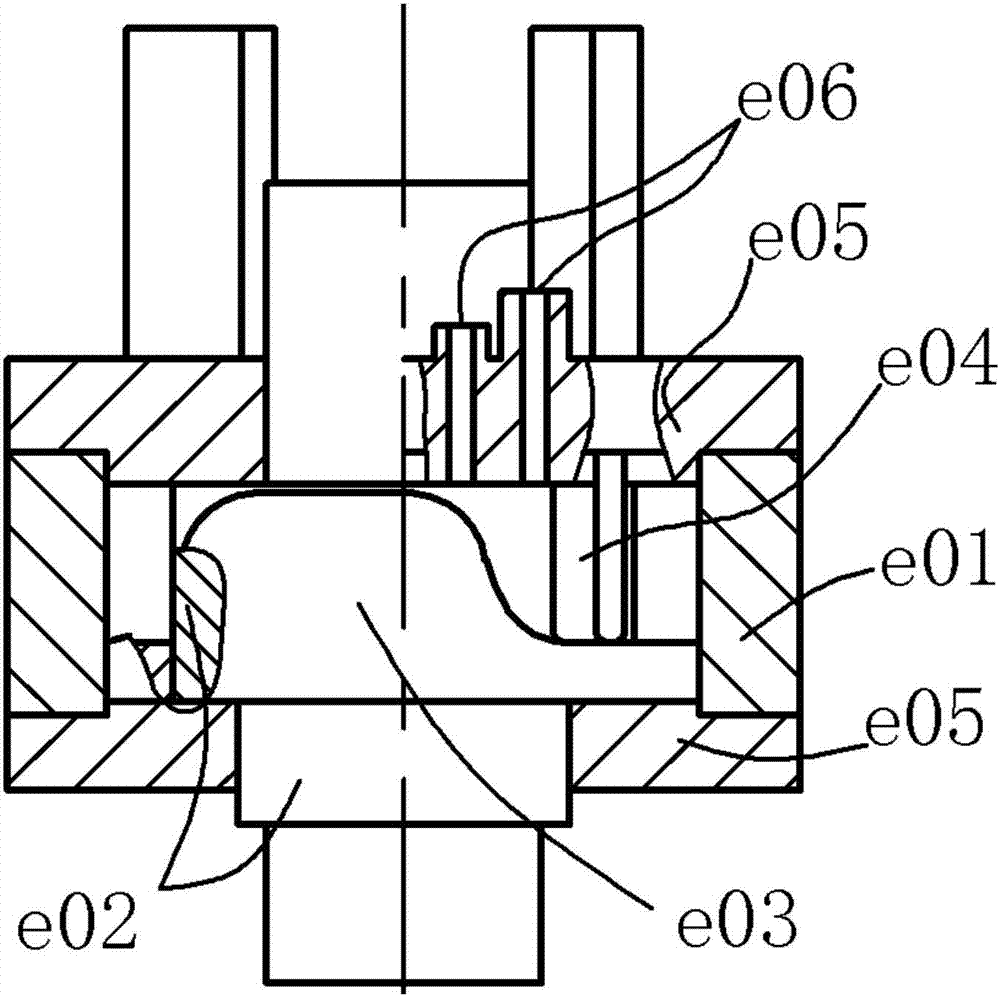
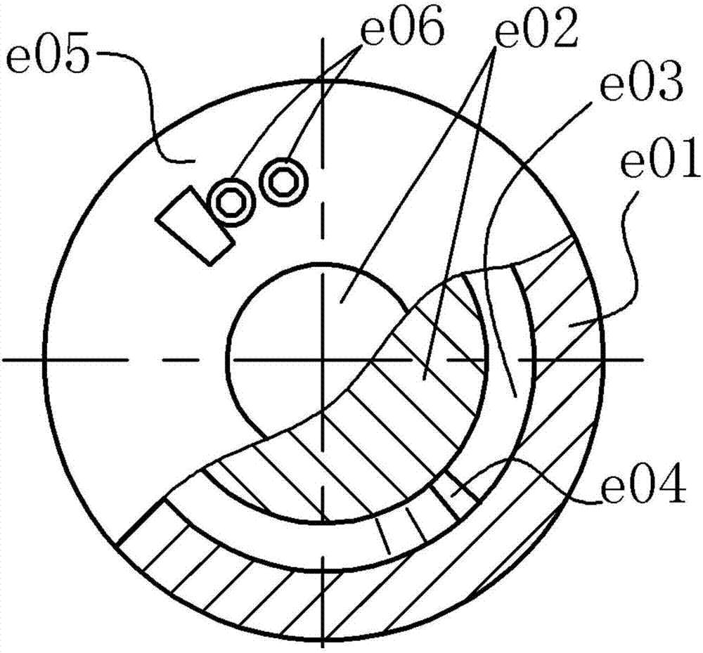
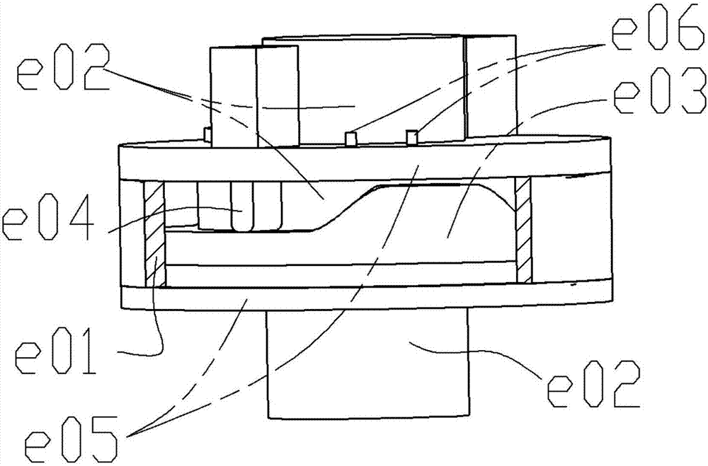
[0040] See Figure 1~3 , assuming that the rotor housing e01 is fixed, the end member e05 is sealed and fixedly connected with the rotor housing e01, and the cylindrical end surface cam e03 and the mandrel e02 are sealed and fixed as a whole to form the rotor; the cam e03 has a far rest area and a near rest area, and the far rest Both the angle of repose and the angle of near repose are slightly less than 180°. The number of sliders e04 is 2, arranged symmetrically. After assembly, the sealing relationship is the same as before and will not be repeated. The inner cylindrical surface of the rotor housing e01, the contour surface of the cam e03, the outer cylindrical surface of the mandrel e02 and the lower end surface of the upper end member e05 form an annular gap with varying height, and the two sliders e04 divide the annular gap into two working chambers. There are two air inlets and two exhaust ports e06, which are located on the end member e05. The more the far resting ...

Embodiment 2

[0052] and then pass Figure 5 and 6 Demonstrate a slightly more complex situation.

[0053] The rotor housing is combined with the end member as a fixed part, and the cylindrical cam and the mandrel are combined as a whole to make the rotor. There are three sliders on the end member to divide the annular gap into three sections evenly. The cylindrical cam has a far rest area and a near rest area respectively. The angle of repose is slightly less than 120°. The space between the two sliders is the working area. cavity or combustion chamber. Figure 5 and 6 The state of the corresponding valve and the working process in the cavity are shown by using the circumferential section development diagram of the working cavity at different positions of the cam. Same as the previous example, with three working chambers, each chamber initially has two possible working processes, so there are 8 different combined working modes. Only two are shown here, and the rest will not be discuss...

Embodiment 3

[0064] Figure 5 Show variability further.

[0065] As long as the circumferential space is large enough, the number of sliders and the number of cam protrusions (such as the far rest area) can be increased arbitrarily. With the addition of a slider escapement, the size of the working space to complete each working cycle can also be varied.

[0066] The parameter relationships selected below are only for the convenience and clarity of description, and are not limiting. In the figure, it is assumed that the far resting sections of the cam rotor are two evenly distributed, and the arc length of the resting sections is slightly larger than the corresponding arc lengths of the two adjacent sliders, so that the two sliders are retracted at the same time. The number of sliders is taken as 6 and evenly distributed, indicated by numbers. Each slider is controlled by the slider escapement, where "out of control" means that the slider has been released by the escapement, "controlled"...


PUM


Abstract

The invention relates to a cylindrical cam rotor internal combustion engine power system and belongs to the field of internal combustion engines. In the power system, a cylindrical cam and a plurality of sliding block driven parts are adopted to form a cam mechanism, and the cylindrical cam, the sliding block driven parts, a rotor chamber, a mandrel and end members form a plurality of circumferentially distributed sealed working chambers; the volumes of the sealed working chambers are changed along with relative movement of the sliding blocks and the cylindrical cam; the four processes of air inflowing, compression, acting and exhausting of an otto cycle are finished in the working chambers through cooperation with air valves; and the chemical energy generated by gas combustion is directly converted into fixed-shaft rotation type mechanical energy of the mandrel relative to the rotor chamber. According to the cylindrical cam rotor internal combustion engine power system, high-pressure gas directly acts on the cylindrical cam and the sliding blocks to generate output power, the structure is simple, and the parameter adjustable range is wide. Flexible control is easy to achieve under control of an added sliding block escapement device, even positive and negative rotation can be achieved, and compared with piston internal combustion engine and Wankel rotor internal combustion engine power systems, the cylindrical cam rotor internal combustion engine power system has much more outstanding advantages.

Description

technical field [0001] The invention belongs to the field of internal combustion engines, and relates to a cylindrical cam rotor internal combustion engine power system. Background technique [0002] The piston internal combustion engine is the earliest internal combustion engine that came out. Its characteristic is that the piston makes a reciprocating linear motion in the cylinder, and the output of the crankshaft rotary motion is realized through the crank slider mechanism. Within two weeks of crankshaft rotation, the cylinder completes a complete intake, compression, work, and exhaust four working processes, that is, the Otto cycle. It is generally believed that the piston internal combustion engine has the advantages of high thermal efficiency, compact structure, strong maneuverability, and easy operation and maintenance. It is even believed that the power device of the piston internal combustion engine, especially the mechanical structure, has reached the peak. Howev...

Claims


Application Information

Patent Timeline
Patent Type & Authority Applications(China)
IPC IPC(8): F02B53/00F02B53/02F02B53/04F02B55/02
CPCF02B53/00F02B53/02F02B53/04F02B55/02Y02T10/12
Inventor 孙守林卞永宁杨扬王琳张光临洪鹏飞
Owner DALIAN UNIV OF TECH
Why Eureka
Try Eureka