Dehumidifier

A dehumidifier and fan technology, which is applied in the field of air dehumidification, can solve the problems of energy waste, increased air duct temperature, and increased working power, and achieve the effects of increasing the working environment temperature, reducing the compressor model, and saving costs

Pending Publication Date: 2017-07-14
NINGBO FREE TRADE ZONE REFINE MOULD TECHNOLOGY CO LTD
View PDF7 Cites 1 Cited by
  • Summary
  • Abstract
  • Description
  • Claims
  • Application Information

AI Technical Summary

Problems solved by technology

The air cooling and condensation time can be extended by extending the air duct, but a longer air duct will inevitably lead to a large volume of the entire dehumidifier, and a corresponding increase in working power
Unavoidable waste of energy
[0004] In addition, the maximum operating temperature of existing dehumidifiers is generally around 40°
When the temperature is higher than 40°, due to the large volume, the temperature of the whole body rises, and the temperature in the air duct also rises accordingly. The longer air duct limits the heat exchange effect and dehumidification effect of the air.

Method used


Image

  • Dehumidifier

Examples


Embodiment Construction

[0022] The specific implementation manners of the present invention will be further described in detail below in conjunction with the accompanying drawings and embodiments. The following examples are used to illustrate the present invention, but are not intended to limit the scope of the present invention.

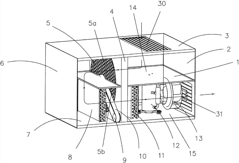
[0023] The structure of a dehumidifier of the present invention is as follows: figure 1 As shown, it includes an upper air passage 14, a lower air passage 15, a runner heat storage body 5, an evaporator 8, a condenser 11, a transmission motor 9 and a fan 13;

[0024] The upper air passage 14 and the lower air passage 15 are isolated by the middle partition 1, the right end of the upper air passage 14 is provided with an air inlet 30, the right end of the lower air passage 1 is provided with an air outlet 31, the left end of the upper air passage 14 and The left end of the lower air duct 15 is connected;

[0025] The upper end of the runner heat storage body 5 is located ...


PUM


Abstract

The invention discloses a dehumidifier. The dehumidifier comprises an upper air flue, a lower air flue, a rotary wheel heat storage body, an evaporator, a condenser, a transmission motor and a fan, wherein the upper air flue is separated from the lower air flue through a middle partition; an air inlet is formed in the right end of the upper air flue; an air outlet is formed in the right end of the lower air flue; the left end of the upper air flue communicates with the left end of the lower air flue; the upper end of the rotary wheel heat storage body is positioned in the upper air flue; the lower end of the rotary wheel heat storage body is positioned in the lower air flue; the transmission motor drives the rotary wheel heat storage body to rotate; and the evaporator, the condenser and the fan are sequentially mounted in the lower air flue from left to right. The dehumidifier disclosed by the invention has the advantages that: energy efficiency of the dehumidifier is greatly improved as the temperature drops and the humidity rises after air is pre-cooled; the area of cool-heat-exchanger is reduced by 30% in comparison with the traditional area, the size of a compressor is also reduced, and the cost is reduced; and the working environment temperature can be further increased to 55 DEG C from original 40 DEG C.

Description

technical field [0001] The invention relates to the field of air dehumidification, in particular to a dehumidifier. Background technique [0002] Dehumidifiers are also known as dehumidifiers, dryers, and dehumidifiers. They can generally be divided into two categories: civil dehumidifiers and industrial dehumidifiers, and belong to a part of the air-conditioning family. Usually, a conventional dehumidifier consists of a compressor, a heat exchanger, a fan, a water tank, a casing and a controller. Its working principle is: the humid air is drawn into the machine by the fan, and passes through the heat exchanger. At this time, the water molecules in the air condense into water droplets, and the dried air after treatment is discharged outside the machine. This cycle keeps the indoor humidity at a suitable level. Relative humidity. [0003] In order to ensure higher heat exchange efficiency and higher dehumidification rate, existing dehumidifiers are generally provided with l...

Claims


Application Information

Patent Timeline
IPC IPC(8): F24F1/02F24F3/14F24F13/30
CPCF24F3/1423F24F13/30F24F2203/104F24F2203/1032
Inventor 周瑞
Owner NINGBO FREE TRADE ZONE REFINE MOULD TECHNOLOGY CO LTD
Why Eureka
Try Eureka