Method and device for measuring dynamic stiffness of resilient element

A dynamic stiffness, elastic element technology, applied in the field of mechanical engineering, can solve the problems of reduced effectiveness, increased elastic force, and inability to obtain accurate elastic element input and output stiffness transfer results, etc.

Active Publication Date: 2017-07-14
SHANGHAI UNIV OF ENG SCI +1
View PDF9 Cites 17 Cited by
  • Summary
  • Abstract
  • Description
  • Claims
  • Application Information

AI Technical Summary

Problems solved by technology

[0015] 1. At high frequencies, the inertial force of the equivalent vibrating mass of the entire test system increases relative to the elastic force of the tested elastic unit, resulting in the inability to obtain accurate stiffness transfer results at the input and output ends of the elastic element;
[0016] 2. When the test frequency is close to or higher than the combined natural frequency of the equivalent participatory mass and the stiffness of the entire test system, since the inertial force of the equivalent participatory mass dominates, the resonance of the entire test system makes it impossible to accurately measure the entire fastener system Dynamic stiffness of
[0019] As far as the fastener system is concerned, its design frequency range is much higher than 30Hz, so the effectiveness of the excitation point measurement method is greatly reduced when it is applied to a low stiffness (<15kN / mm) fastener system. The present invention aims to improve the accuracy of the measurement results Frequency Range and Accuracy

Method used


Image

  • Method and device for measuring dynamic stiffness of resilient element
  • Method and device for measuring dynamic stiffness of resilient element
  • Method and device for measuring dynamic stiffness of resilient element

Examples


Embodiment 1

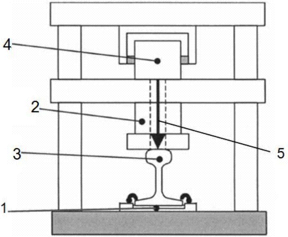
[0059] Such as Figure 7-10Described, a dynamic stiffness measuring device of an elastic unit, comprising an elastic unit 1, a loaded vibration isolation spring 2, a rail 3, a vibrator 4, a single-frequency resonance signal generator 101, a power amplifier 102, an upper beam 103, and a column 104 , exciter rod 105, lower beam 106, upper positioning plate 107 of the isolation spring, lower positioning plate 108 of the isolation spring, force sensor 109, acceleration sensor 110, rigid base 111, signal adjustment acquisition and processing system 112, the elastic unit 1 is arranged between the rigid base 111 and the rail 3, the rigid base 111 is connected to the upper beam 103 and the lower beam 106 through the column 104, and the loading vibration isolation spring 2 is arranged on the isolation spring, the positioning plate 107 and the isolation spring Between the lower positioning plates 108, wherein the upper positioning plate 107 of the isolation spring is arranged at the bot...

Embodiment 2

[0085]The test and correction method are the same as in Example 1, except that the lower positioning plate 108 of the rail 3 and the isolation spring in the test device is replaced by a low-density high-strength alloy material and the lower positioning plate of the steel isolation spring, and the head of the rail is cut flat to Reduce the quality of vibration participation, as shown in Figure 8 is the steel rail 3 with the head flattened, such as Figure 9-10 Shown is the lower positioning plate 108 corresponding to the light-duty optimized isolation spring, so that the equivalent connecting piece mass m 11 Reduced to 25% of the original, so the effective frequency upper limit is increased by about 2 times.


PUM


Abstract

The invention relates to a method and a device for measuring the dynamic stiffness of a resilient element. The dynamic stiffness of a resilient element is measured using an excitation point measurement method in ISO 10846-5. First, the dynamic stiffness k11 of an excitation point is obtained. Then, the test system equivalent vibration mass inertia stiffness Omega<2>m1 and the test system equivalent support stiffness ki are measured, and the dynamic stiffness k21 of the resilient element after modification is calculated according to the formula: k21=k11+Omega<2>m1-ki. In addition to devices adopted in the excitation point measurement method in ISO 10846-5, the device comprises a single-frequency resonant signal generator (101), a power amplifier (102), an isolation spring upper positioning plate (107), an isolation spring lower positioning plate (108), a force sensor (109), an acceleration sensor (110), and a signal conditioning, collecting and processing system (112). Compared with the prior art, through second measurement carried out on the basis of first measurement, the accuracy of the dynamic stiffness measurement result and the applicable frequency range are improved effectively.

Description

technical field [0001] The invention relates to any mechanical engineering field including the technical field of railway tracks, and proposes a testing method and a testing device for improving the frequency range and measurement accuracy of dynamic stiffness of an elastic unit. Background technique [0002] Because the complex elastic unit of the track generally contains not only elasticity but also mass and damping, etc., the dynamic stiffness includes not only the direct stiffness but also the cross stiffness, which can be expressed in the form of a matrix, such as figure 1 shown. The basic principle of measuring the dynamic stiffness 1 of the elastic unit is to obtain the dynamic stiffness of the elastic unit by measuring the input or output force F and the input or output displacement u (or velocity or acceleration). [0003] The current general elastic element dynamic stiffness measurement method and test device are in accordance with the international standard ISO10...

Claims


Application Information

Patent Timeline
Patent Type & Authority Applications(China)
IPC IPC(8): G01M5/00
CPCG01M5/0066
Inventor 王安斌周伦彬
Owner SHANGHAI UNIV OF ENG SCI
Why Eureka
Try Eureka