Annular focusing light spot realization method and realization device thereof

A technology of focusing spot and realization method, which is applied in the field of optics, can solve problems such as discontinuous changes, and achieve the effect of precise control of position and size

Active Publication Date: 2017-07-14
唐山斯腾光电科技有限公司
View PDF5 Cites 22 Cited by
  • Summary
  • Abstract
  • Description
  • Claims
  • Application Information

AI Technical Summary

Problems solved by technology

But there is no way to focus the vortex linearly polarized beam to produce a circularly symmetrical ring spot
Moreover, the size of the annular spot can only be changed by changing the integer value of the topological charge, and this change is discontinuous

Method used


Image

  • Annular focusing light spot realization method and realization device thereof
  • Annular focusing light spot realization method and realization device thereof
  • Annular focusing light spot realization method and realization device thereof

Examples


Embodiment Construction

[0041] In order to make the purpose, technical solutions and advantages of the embodiments of the present invention clearer, the technical solutions in the embodiments of the present invention will be clearly and completely described below in conjunction with the drawings in the embodiments of the present invention. Obviously, the described embodiments It is a part of embodiments of the present invention, but not all embodiments.

[0042] A method for realizing an annular focus spot of the present invention comprises the following steps:

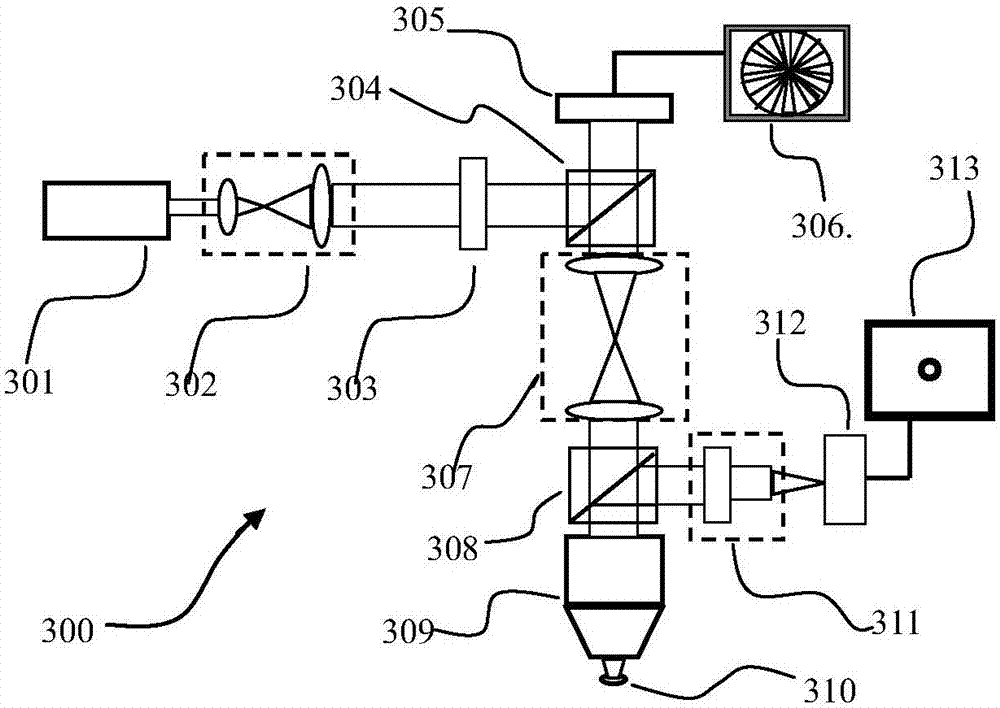
[0043] Step S1: converting the laser beam with arbitrary polarization into a linearly polarized laser beam after beam expansion and collimation;

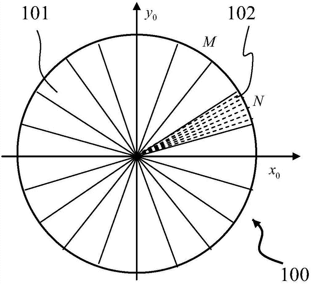
[0044] Step S2: performing laser beam phase modulation on the linearly polarized laser beam after collimation and beam expansion using a reflective phase-only spatial light modulator;

[0045] Step S3: Imaging the phase-modulated linearly polarized light onto the rear aperture plane of the focusi...


PUM


Abstract

The invention discloses an annular focusing light spot realization method. The method includes that a laser beam is expanded and collimated and then the expanded and collimated laser beam is converted into a linearly polarized laser beam; the laser beam phase modulation is carried out on the linearly polarized laser beam after the collimation and expansion by means of a reflective pure phase spatial light modulator; the linearly polarized light is imaged after the phase modulation to the rear aperture plane of a focusing object lens via a 4F imaging system; the object lens is used to focus the phase-modulated incident linearly polarized laser beam, a plurality of focal points are generated on the circumference in the focal plane area, and the azimuthal spacing between the focal points equal is equal; an annular light spot is generated when the circumference radius is reduced to a wavelength lambda, and the size of the annular light spot is continuously decreased when the circumference radius r changes until a solid light spot is formed; and when a plurality of phase modulation graphs are calculated, the change in the corresponding position movement of each graph is small, and the phase map of the spatial light modulator is updated so that the annular light spot moves continuously. The annular focusing light spot realization method realizes the non-vortex plane linearly polarized light focusing to generate the dynamic annular light spot which is accurate in position and size control.

Description

technical field [0001] The present invention relates to the field of optics, in particular to a method and device for realizing an annular focus spot. The laser beam is focused by a high numerical aperture objective lens to produce a special shape, and an annular focus with controllable position and changeable size on the focal plane is produced. spot. Background technique [0002] The laser beam is focused by a high numerical aperture objective lens, and its spot shape, position, phase distribution, intensity distribution, and polarization distribution are related to the amplitude distribution, polarization state, phase modulation of the incident laser beam, and the numerical aperture of the objective lens. Since the spot produced by laser focusing through the objective lens is related to many application fields, it has become a very important research field to study how to achieve the laser focusing spot required by various applications by changing the amplitude distributi...

Claims


Application Information

Patent Timeline
Patent Type & Authority Applications(China)
IPC IPC(8): G02B27/09G02B27/28
CPCG02B27/09G02B27/28
Inventor 陈建农朱林伟李志刚徐钦峰
Owner 唐山斯腾光电科技有限公司
Why Eureka
Try Eureka