Light beam coupling device

A coupling device and beam technology, applied in the field of spectral measurement, can solve the problems of poor beam coupling effect, affecting detection function, unable to effectively realize beam combining, etc., to achieve the effect of coupling

Inactive Publication Date: 2017-07-14
LIHE TECH (HUNAN) CO LTD
View PDF8 Cites 3 Cited by
  • Summary
  • Abstract
  • Description
  • Claims
  • Application Information

AI Technical Summary

Problems solved by technology

There are many existing beam coupling devices, but due to the limitations in the structural design of the existing beam coupling devices, the existing beam coupling devices often cannot effectively realize the beam combining, and the coupling effect of the beams is poor, which greatly affects its later stage. detection function

Method used


Image

  • Light beam coupling device
  • Light beam coupling device
  • Light beam coupling device

Examples


Embodiment 1

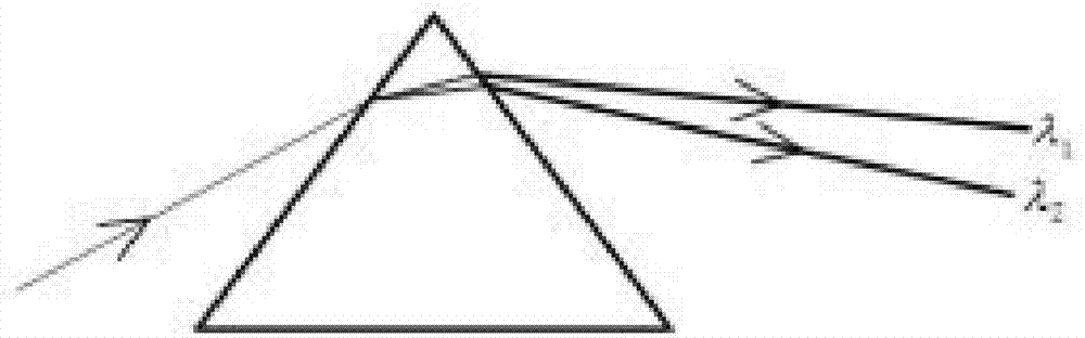
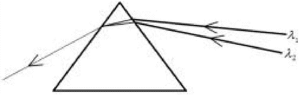
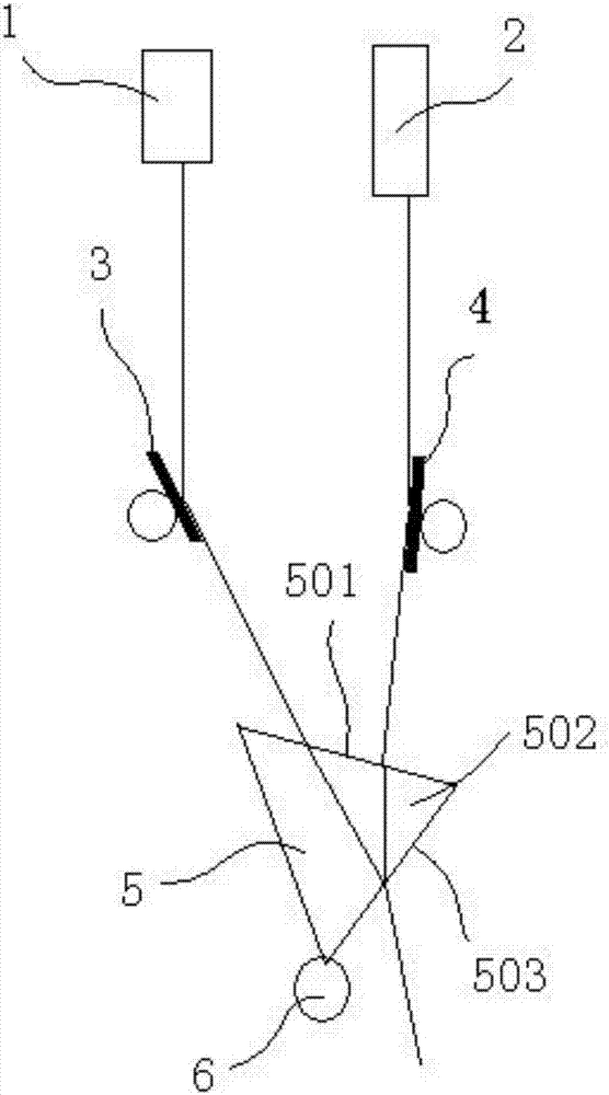
[0028] see Figure 1 to Figure 3 , Figure 1 to Figure 3 A specific embodiment of a beam coupling device of the present invention is provided, wherein, figure 1 and figure 2 It is an optical principle diagram of the beam coupling device disclosed in Embodiment 1 of the present invention; image 3 It is a schematic structural diagram of the beam coupling device disclosed in Embodiment 1 of the present invention.

[0029] Such as Figure 1 to Figure 3 As shown, a beam coupling device provided by the present invention cleverly utilizes the principle of reflection and refraction of beams to construct a beam coupling device composed of a transmitting mechanism, an adjusting mechanism and a beam combining mechanism, which can effectively realize the coupling of different wavelength beams. The energy loss is small.

[0030] In this embodiment, the principle of refraction is as follows figure 1 and figure 2 as shown, figure 1 , when a whole beam containing wavelengths λ1 and...

Embodiment 2

[0046] see Figure 4 , Figure 4 Another specific embodiment of a beam coupling device of the present invention is provided, wherein, Figure 4 It is a schematic structural diagram of the beam coupling device disclosed in Embodiment 2 of the present invention.

[0047] Other parts of this embodiment are the same as Embodiment 1, the difference is that in order to further facilitate the control of different light beams to shoot at the beam combining mechanism at a specified angle, a relay mirror 7 is arranged between the adjusting mechanism and the beam combining mechanism, and the relay The reflector 7 is used to receive all the light beams transmitted by the adjustment mechanism and direct the light beams to the beam combination mechanism at a specified angle.

[0048] In this embodiment, the emitting mechanism is a laser emitter, including a left laser emitter 1 and a right laser emitter 2, a left reflector 3 is arranged directly below the left laser emitter 1, and a left ...

Embodiment 3

[0053] see Figure 5 , Figure 5 A third specific embodiment of a beam coupling device of the present invention is provided, wherein, Figure 5 It is a schematic structural diagram of the beam coupling device disclosed in Embodiment 3 of the present invention.

[0054] Other parts of the present embodiment are the same as Embodiment 2, except that the triangular prism is provided with at least two, 5 layers of triangular prisms are arranged at intervals and the outgoing face of the triangular prism of the upper floor is parallel to the incident face of the triangular prism of the lower floor.

[0055] In this embodiment, there are two triangular prisms 5, which are an upper triangular prism and a lower triangular prism respectively, and the output surface of the upper triangular prism is parallel to the incident surface of the lower triangular prism. Therefore, it is more convenient for the beam to be synthesized into a whole beam after multiple refractions.

[0056] In thi...


PUM


Abstract

The invention discloses a light beam coupling device. The light beam coupling device comprises: at least two emitting mechanisms, wherein the emitting mechanisms are used for emitting light beams, and the different emitting mechanisms are used for emitting light beams with different prescribed wavelengths; an adjusting mechanism, which is arranged in a light beam emitting direction of the emitting mechanisms and is used for adjusting directions of light beams so that light beams emitted from the emitting mechanisms are emitted in a prescribed direction; and a beam combining mechanism, which is a dispersing prism and is arranged in the light beam transmission direction of the adjusting mechanism, wherein the dispersing prism is used for receiving all light beams from the adjusting mechanism and adjusting incoming angles of the light beams different in wavelength so that the light beams are combined to be a whole light beam when being refracted to be sent out. The light beam coupling device, with the structural design, is capable of effectively coupling light beams different in wavelength.

Description

technical field [0001] The present invention relates to the technical field of spectrum measurement, and more specifically, relates to a beam coupling device. Background technique [0002] TDLAS refers to Tunable Diode Laser Absorption Spectroscopy, which is the abbreviation of Tunable Diode Laser Absorption Spectroscopy. This technology mainly uses the characteristics of narrow line width and wavelength change with injection current of tunable semiconductor lasers to realize single or several distances of molecules very close. Difficult to resolve absorption lines are measured. TDLAS technology is a highly selective and high-resolution spectroscopic technique, which is not interfered by other gases due to the "fingerprint" characteristics of molecular spectra. TDLAS technology is a universal technology that is effective for all active molecules that absorb in the infrared. The same instrument can be easily changed to an instrument for measuring other components, only need ...

Claims


Application Information

Patent Timeline
Patent Type & Authority Applications(China)
IPC IPC(8): G02B27/10G02B27/12
CPCG02B27/1006G02B27/126
Inventor 刘海东刘德华彭文姣
Owner LIHE TECH (HUNAN) CO LTD
Why Eureka
Try Eureka