Active and reactive coordination optimization control method of distributed photovoltaic power distribution network
A distributed photovoltaic, optimized control technology, applied in photovoltaic power generation, reactive power adjustment/elimination/compensation, reactive power compensation, etc., can solve the problem that the control method cannot be applied to distribution lines, and cannot be coordinated and optimized control of active and reactive power.
Active Publication Date: 2017-07-14
CHINA AGRI UNIV
2 Cites 30 Cited by
AI-Extracted Technical Summary
Problems solved by technology
[0005] The present invention provides an active and reactive power coordination optimization control method that overcomes the above-mentioned problems or at least partially solves the above-mentioned problems, and solves the problem that the existing control methods cannot be applied to large R/X ratios, active and reactive power In the power dis...
Method used
In summary, the application proposes a method for coordinating and optimizing the active and reactive power of a distributed photovoltaic distribution network, and divides the control process of the system into long-term scale optimization control and short-time scale optimization control. Different time scales Optimal control performs separate model predictive control for their respective control objectives and control variables. The long-term scale is based on photovoltaic output and load demand forecast information, and multi-step rolling optimization is used to solve the active and reactive power output of each controllable device. The short-term scale is as follows: The calculation result of the long-term scale is the reference value, and the active and reactive output increment is calculated rollingly. It can effectively cope with the fluctuation of photovoltaic output and load demand, comprehensively consider a variety of more controllable devices in the power distribution system, effectively deal with the overvoltage phenomenon of the power distribution system caused by phot...
Abstract
The invention provides an active and reactive coordination optimization control method of a distributed photovoltaic power distribution network. The method comprises steps that S1, based on the model predictive control method, according to the control targets and the control variables of different time scales, the distribution network system control process is divided into the long time scale optimization control and the short time scale optimization control, and a long time scale optimization control model and a short time scale optimization control model are established; S2, solving problems of the long time scale optimization control and the short time scale optimization control are converted into second-order cone programming problems; and S3, the long time scale optimization control model is based on the photovoltaic output and the load demand forecasting information, and uses the multi-step rolling optimization to solve the active and reactive power output of each controllable device, and the short time scale optimization control model is used to calculate the active and reactive power increment of each controllable device in a rolling manner with the solving result of the long time scale optimization control model as the reference value.
Application Domain
Single network parallel feeding arrangementsReactive power adjustment/elimination/compensation +3
Technology Topic
Control variableSecond-order cone programming +10
Image
Examples
- Experimental program(1)
Example Embodiment
[0056] The specific embodiments of the present invention will be described in further detail below with reference to the accompanying drawings and embodiments. The following examples are intended to illustrate the present invention, but not to limit the scope of the present invention.
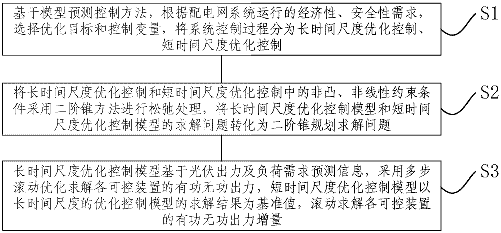
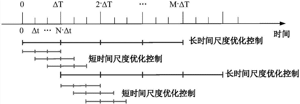
[0057] like figure 1 and figure 2 As shown, the figure shows a coordinated optimal control method for active and reactive power in a distributed photovoltaic power distribution network, including:
[0058] S1. Based on the model predictive control method, according to the control objectives and control variables of different time scales, the system control process is divided into long-time scale optimal control and short-time scale optimal control, and the long-time scale optimal control model and short-time scale optimization control model are established. control model;
[0059] S2. Use the second-order cone method to relax the non-convex and nonlinear constraints in the long-time-scale optimal control and the short-time-scale optimal control, and transform the solution problem of the long-time-scale optimal control model and the short-time-scale optimal control model Solve the problem for the second-order cone programming;
[0060] S3. The long-time-scale optimal control model is based on the photovoltaic output and load demand forecast information, and uses multi-step rolling optimization to solve the active and reactive power output of each controllable device. The short-time-scale optimal control model is based on the long-term optimal control model. As the reference value, the active and reactive output increments of each controllable device are calculated in a rolling manner.
[0061] Preferably, the step S1 specifically includes:
[0062] S11. Based on the model predictive control method, the control process is divided into long-time-scale optimal control and short-time-scale optimal control, and a long-time-scale optimal control model is established according to the long-time-scale optimal control to ensure the economical optimization purpose of system operation; The optimization purpose of short-time-scale optimal control to ensure the safety of system operation, establish a short-time-scale optimal control model;
[0063] S12. According to the optimization purposes of the long-time-scale optimal control model and the short-time-scale optimal control model, select the optimization objectives of the long-time-scale optimal control model and the short-time-scale optimal control model;
[0064] S13 , respectively setting constraints of the long-time scale optimal control model and the short-time scale optimal control model according to the optimization objective.
[0065] Preferably, the step S11 specifically includes:
[0066] Based on the model predictive control method, based on the forecast data of photovoltaic output and load demand, with ΔT as the time interval, a long-term scale optimization control model is established, and the active and reactive power output of each controllable device in the system in the future M·ΔT time period is calculated in a rolling manner. ;
[0067] Based on the model predictive control method, according to the current system operating state and the forecast data of photovoltaic output and load demand on a smaller time scale, with Δt as the time interval, an optimal control model on a short time scale is established, and the rolling solution of the system in the future N·Δt time period is calculated. Active and reactive output of each controllable device;
[0068] The M and N are respectively the control step size of the long-time-scale optimal control model and the short-time-scale optimal control model, Δt
[0069] Preferably, the step S12 includes:
[0070] In the long-time-scale optimal control model, the optimization goal is to minimize the network loss of the distribution network system, and by calculating t 0 to t 0 The sum of the network losses of each branch line in the +M·ΔT time period is used to calculate the network loss of the distribution network system, t 0 Rolling optimization start times for long-time-scale optimization control models;
[0071] In the short-time-scale optimal control model, the optimization goal is to minimize the network loss of the distribution network system, and by calculating t 0 to t 0 The sum of the network loss of each branch line in the +M·Δt time period calculates the network loss of the distribution network system.
[0072] In this embodiment, in order to ensure the economy of the system operation and reduce the network loss, the optimization objective of the long-time-scale optimal control is to minimize the system network loss, and the calculation formula is:
[0073]
[0074] i ij,t =f(K ij,t ,H c,i,t ,P ch,i,t ,P dis,i,t ,Q DG,i,t ,Q SVC,i,t ) (1)
[0075] In the formula, minF is the minimum value of the system network loss; t 0 is the starting time of the long-term rolling optimization, ΔT is the time interval of the long-term optimization control, M is the control step, n is the number of nodes, r ij is the resistance of line ij, i ij,t is the square of the current of the line ij at time t, expressed as a function of each controllable variable; c(i) represents the set of all line end nodes with i as the first node of the line; K ij,t The adjustable gear of the on-load voltage regulating transformer; H c,i,t Adjust the gear for the compensation capacitor bank; P ch,i,t , P dis,i,t are the charging and discharging power of the energy storage device; Q DG,i,t , Q SVC,i,t Represents the reactive power of distributed photovoltaic and static reactive power compensation device at node i at time t, respectively.
[0076] S13. Set constraints; the constraints of the long-time-scale optimal control model include power flow constraints, voltage level constraints, branch capacity constraints, distributed photovoltaic operation constraints, on-load voltage regulation transformer operation constraints, and static reactive power compensation device operation constraints , Compensation capacitor bank operation constraints and energy storage device operation constraints;
[0077] Specifically, for a radiating distribution network, the power flow constraint adopts the Distflow form to express the power flow equation:
[0078]
[0079]
[0080]
[0081]
[0082]
[0083] α(j) represents the set of branch end nodes with node i as the head node; β(i) represents the set of branch end nodes with node j as the head node; P ij,t , Q ij,t are the active power and reactive power at the head end of branch ij at time t, respectively; P j,t , Q j,t are the injection values of active power and reactive power at node j at time t, respectively; P DG,j,t , Q DG,j,t are the active power and reactive power injected by distributed photovoltaics at node j at time t, respectively; P load,j,t , Q load,j,t are the active power and reactive power consumed by the load at node j at time t, respectively; P ch,i,t , P dis,i,t are the charging and discharging power of the energy storage device; Q SVC,j,t , Q c,j,tare the reactive power of the static reactive power compensation device and the compensation capacitor bank at node j at time t, respectively; r ij +jx ij is the sum of the impedance of the branch ij and the on-load voltage regulating transformer on the line; I ij,t is the amplitude of the current flowing through the branch ij at time t; V i,t is the voltage amplitude of node i at time t; k ij,t is the transformation ratio of the on-load voltage regulating transformer at the branch ij at time t; v i,t , i ij,t are the square of the voltage amplitude at node i and the square of the current amplitude of branch ij at time t, respectively;
[0084] Voltage level constraints:
[0085] V i min ≤V i,t ≤V i max (7)
[0086] In the formula, are the upper and lower limits of the node i voltage amplitude, respectively.
[0087] Branch capacity constraints:
[0088]
[0089] In the formula, is the upper limit of the current amplitude of branch ij.
[0090] Distributed photovoltaic operation constraints:
[0091]
[0092]
[0093]
[0094] In the formula, is the predicted value of distributed photovoltaic active power output at node i at time t, are the upper and lower limits of the distributed photovoltaic reactive power output at node i at time t, respectively, S DG,i is the capacity of distributed photovoltaics at node i.
[0095] On-load regulator transformer (OLTC) operating constraints:
[0096] k ij,t =k 0 +K ij,t Δk ij (12)
[0097]
[0098] In the formula, k 0 is the OLTC standard transformation ratio, Δk ij Adjust the step size for OLTC, K ij,t , are the OLTC adjustable gear and its upper and lower limits at time t, respectively.
[0099] Static var compensation (SVC) operating constraints:
[0100]
[0101] In the formula, They are the upper and lower limits of SVC adjustable reactive power output, respectively.
[0102] Compensation capacitor bank operating constraints:
[0103]
[0104] In the formula, H i,t In order to compensate the adjustable gear of the capacitor bank, ΔQ c,i,t In order to adjust the step size, n is the maximum adjustable gear.
[0105] Energy storage device operating constraints:
[0106]
[0107]
[0108]
[0109] In the formula, E i,t Represents the power of the energy storage device; P ch,i,t , P dis,i,t respectively represent the charging and discharging power of the energy storage device; η ch , n dis respectively represent the charge and discharge efficiency of the energy storage device; D ch,i,t , D dis,i,t is a 0-1 variable, and constraint (18) ensures that the charging and discharging of the energy storage device will not occur simultaneously; is the charging limit of the energy storage device.
[0110] The constraints of the short-time-scale optimal control model include power flow constraints, voltage level constraints, branch capacity constraints, distributed photovoltaic operation constraints, static reactive power compensation device operational constraints and energy storage device operational constraints. Due to the large random fluctuation of photovoltaic output and load demand, the long-term prediction data has large errors and cannot meet the accuracy requirements. Therefore, short-time-scale optimal control is added. Based on the current operating state of the system and the prediction data on a shorter time-scale Adjust the optimal control results of the scale, and take Δt as the time interval to calculate the active and reactive power output of each controllable device in the system in the future N·Δt time period, where M and N are the long-term optimal control and short-term The control step size of the scale optimization control, Δt < ΔT; the response speed of the on-load voltage regulating transformer and the compensation capacitor bank is slow, and the adjustment should not be too frequent, so the two are not adjusted in the short-time scale optimal control, and the control variable is the storage It can install charge and discharge power increments, static reactive power compensation devices and distributed photovoltaic reactive power increments.
[0111] Since the error of the photovoltaic output and load demand forecast data increases with the advance of the forecast time, in order to cope with the random fluctuation of the two, prevent the voltage exceeding the limit, ensure the safety of the system operation, and at the same time ensure the overall optimization of the long-term scale. The direction and the consistency of analysis and calculation, the short-time scale optimization control still takes the minimum system network loss as the optimization goal, and its calculation formula is:
[0112]
[0113]
[0114] In the formula, minF is the minimum value of system network loss; Δt is the time interval of short-time-scale optimal control, N is the control step size of short-time-scale optimal control, Represents the charging and discharging power of the energy storage device at time t; Respectively represent the reference value of the long-term optimal control of the reactive power output of distributed photovoltaic and static reactive power compensation devices; ΔP ch,j,t , ΔP dis,j,t , ΔQ DG,j,t , ΔQ SVC,j,t Respectively represent the adjustment value of the charging and discharging power of the energy storage device optimally controlled on a short time scale at time t, and the adjustment value of the reactive output of the distributed photovoltaic and static reactive power compensation devices.
[0115] In the short-time-scale optimization control, the constraint variables include power flow constraints, voltage level constraints, branch capacity constraints, distributed photovoltaic operation constraints, static reactive power compensation device operation constraints, and energy storage device operation constraints; specifically:
[0116] Tide Constraints:
[0117]
[0118] Other constraints, including voltage level constraints, branch capacity constraints, distributed photovoltaic operation constraints, static reactive power compensation device operation constraints, and energy storage device operation constraints;
[0119]
[0120] Both long-term and short-time-scale optimal control are advanced predictive control based on predictive information. Due to the uncertainty of photovoltaic output and load demand, there is often a deviation between the measured value and the predicted value of the system. Therefore, through feedback correction, the The measured output value is fed back to the long-time-scale optimal control and the short-time-scale optimal control with feedback information, which is used as the initial value of the next round of rolling optimization to realize closed-loop control and make the prediction result closer to the actual value.
[0121] Considering various controllable devices such as on-load voltage regulating transformer, compensation capacitor, static reactive power compensation device, distributed photovoltaic, energy storage device, etc. in the system, the control process is divided into long-time scale optimal control and short-time scale optimal control . The long-time-scale optimal control ensures the economy of the system operation, and the short-time-scale optimal control ensures the safety of the system operation. The two implement separate model predictive control based on their respective optimization objectives. The long-term scale optimization control takes the minimum system network loss as the optimization goal, based on the forecast data of photovoltaic output and load demand, and takes ΔT as the time interval to optimize the active and reactive power output of each controllable device in the system in the future M·ΔT time. Solve, as the adjustment base point of the short-time-scale optimization control layer. Short-time-scale optimal control According to the current system operating state and the forecast data of photovoltaic output and load demand on a smaller time-scale, with Δt (Δt < ΔT) as the time interval, the rolling solution of the controllable devices in the system in the future N·Δt time is calculated. The increase of active and reactive power output is used to correct the previous optimization results. control structures such as figure 2 shown.
[0122] In this embodiment, the optimization problem includes both continuous variables and integer variables. Its mathematical nature is a mixed integer non-convex and nonlinear optimization problem, and it is difficult to obtain the optimal solution. This paper considers transforming the optimization model into an efficient solution. The second-order cone programming (SOCP) problem.
[0123] In the step S2, the form of the second-order cone planning is:
[0124]
[0125] In the formula, the variable x∈R N; constant b∈R M , c∈R N , A∈R M×N; K is a second-order cone or a rotating second-order cone.
[0126] Preferably, the second-order conical formula is:
[0127]
[0128] The rotating second-order cone formula is:
[0129]
[0130] Taking the long-time-scale optimal control as an example, equations (3) and (4) in the power flow constraints are non-convex and nonlinear equations, and the optimization objective function and other constraints are linear equations. its processed.
[0131] Equations (3) and (13) are constraints on the OLTC. The exact linearization modeling method based on piecewise linearization is used to model the OLTC, and the constraints are transformed into linear constraints.
[0132] Equation (4) is relaxed by the second-order cone method. After relaxation, Equation (4) can be rewritten as:
[0133]
[0134] Rewrite it in the standard second-order conical form, that is:
[0135] ||[2Pi j,t 2Q ij,t i ij,t -v i,t ] T || 2 ≤i ij,t +vi,t (26)
[0136] The long-time-scale optimal control model contains discrete variables and continuous variables, and the optimal model is finally transformed into a mixed integer second-order cone programming model; the short-time-scale optimal control model only includes continuous variables and is finally converted into a second-order cone programming model.
[0137] The present embodiment also shows a distributed photovoltaic power distribution network active and reactive power coordination optimization system, including a long-time-scale optimal control model and a short-time-scale optimal control model;
[0138] The long-time-scale optimal control model is used to take the minimum system network loss as the optimization goal, and based on the forecast data of photovoltaic output and load demand, with ΔT as the time interval, to calculate the active and non-active power of each controllable device in the future M·ΔT time. power output;
[0139] The short-time-scale optimal control model is used to adjust the long-term optimal control results based on the current operating state of the system and the forecast data on a shorter time-scale. Taking Δt (Δt < ΔT) as the time interval, the future N· The increment of active and reactive power output of each controllable device in the system within the time Δt.
[0140] To sum up, this application proposes a coordinated optimal control method for active and reactive power in a distributed photovoltaic power distribution network, which divides the control process of the system into long-time-scale optimal control and short-time-scale optimal control. The respective control objectives and control variables perform separate model predictive control. Based on the photovoltaic output and load demand forecast information on the long-term scale, multi-step rolling optimization is used to solve the active and reactive power output of each controllable device. The calculation result of is the reference value, and the active and reactive output increments are calculated in a rolling manner. It can effectively deal with the fluctuation of photovoltaic output and load demand, comprehensively consider a variety of more controllable devices in the power distribution system, effectively deal with the overvoltage phenomenon of the power distribution system caused by photovoltaic access, reduce network losses, and ensure the safety and economy of the system. At the same time, through the coordination of multiple time scales, it is ensured that the adjustment times of slow-motion equipment will not be too frequent, thereby ensuring its service life and reducing equipment purchase expenses in the distribution network; by making full use of the reactive power output of distributed photovoltaics , without reducing the active power of distributed photovoltaics, greatly improving the consumption of distributed photovoltaics in the distribution network, and reducing the system's absorption of active and reactive power from the large power grid. The long-term and short-time-scale rolling optimization control includes both continuous variables and integer variables, and its mathematical essence is a mixed integer non-convex and nonlinear optimization problem, and it is difficult to obtain the optimal solution. Efficiently solve the second-order cone programming problem, making the calculation easier and more efficient.
[0141] Finally, the method of the present application is only a preferred embodiment, and is not intended to limit the protection scope of the present invention. Any modification, equivalent replacement, improvement, etc. made within the spirit and principle of the present invention shall be included within the protection scope of the present invention.
PUM


Description & Claims & Application Information
We can also present the details of the Description, Claims and Application information to help users get a comprehensive understanding of the technical details of the patent, such as background art, summary of invention, brief description of drawings, description of embodiments, and other original content. On the other hand, users can also determine the specific scope of protection of the technology through the list of claims; as well as understand the changes in the life cycle of the technology with the presentation of the patent timeline. Login to view more.