Flexibly adjustable FIR audio digital frequency divider

A digital frequency divider and a technology for adjusting parameters, applied in pulse counters, digital technology networks, counting chain pulse counters, etc. Effect

Active Publication Date: 2017-07-14
SHENZHEN TENDZONE INTELLIGENT TECH
4 Cites 0 Cited by

AI-Extracted Technical Summary

Problems solved by technology

At present, although there are digital frequency dividers designed with FIR filters, the number is very small, the application field is narrow, and it cannot be adjusted flexibl...

Method used

On the basis of embodiment 2, the quantity of described FIR module is 4. With this technical solution, the flexible adjustable FIR audio digital frequency divider can obtain single-channel filters, tw...

Abstract

The invention relates to a flexibly adjustable finite impulse response (FIR) audio digital frequency divider. The flexibly adjustable FIR audio digital frequency divider comprises an operation unit and a configuration unit, wherein the operation unit comprises a route module and at least two FIR modules, the route module comprises an on-off parameter for controlling whether to connect with each FIR module, and each FIR module comprises an adjustment parameter involving in a frequency division process; the on-off parameter and the adjustment parameter are firstly configured and then are transmitted to the route module and each FIR module through the configuration unit, next a data flow enters an FIR module which is switched on by the route module, and the data flow is subject to frequency division and then is outputted. In use, the on-off parameter and the adjustment parameters are firstly configured and secondly transmitted to the operation unit through the configuration unit, and the operation unit performs frequency division process on the data flow and then outputs the processed data flow. By adopting the technical scheme of the invention, each parameter in a frequency division processing procedure can be flexibly adjusted in order to meet different frequency division requirements.

Application Domain

Digital technique networkCounting chain pulse counters

Technology Topic

Audio frequencyFrequency division duplex +4

Image

  • Flexibly adjustable FIR audio digital frequency divider
  • Flexibly adjustable FIR audio digital frequency divider
  • Flexibly adjustable FIR audio digital frequency divider

Examples

  • Experimental program(3)

Example Embodiment

[0028] Example 1
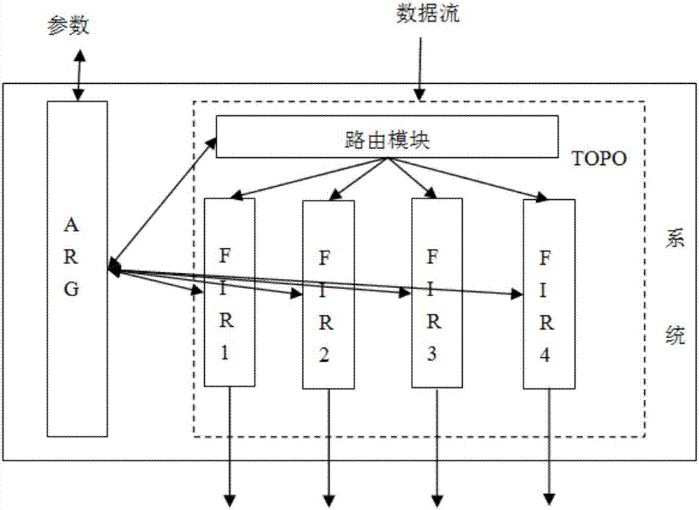
[0029] This flexibly adjustable FIR audio digital frequency divider includes an arithmetic unit and a configuration unit. The arithmetic unit includes a routing module and no less than 2 FIR modules. The routing module includes a switch that controls whether to connect to each FIR module. Parameters, each FIR module includes adjustment parameters involved in frequency division processing. The switch parameters and adjustment parameters are set first, and then transmitted to the routing module and each FIR module through the configuration unit, and then the data stream enters the routed The FIR module opened by the module is output after frequency division processing.
[0030] Such as figure 1 As shown, the computing unit is a TOPO file, the configuration unit is an ARG file, the computing unit includes 1 routing module and 4 FIR modules, and the FIR modules are FIR1, FIR2, FIR3, and FIR4, respectively; Wherein, the routing module includes switch parameters that control whether to connect with each FIR module, and the FIR module includes adjustment parameters involved in frequency division processing; when using, first set the switch parameters and adjustment parameters, and pass the ARG unit It is transmitted to the routing module and each FIR module, and then the data stream enters the channel of the FIR module opened by the routing module, and is output after frequency division processing.
[0031] Among them, the FIR module refers to a module that performs processing operations on data streams through FIR filters. The formula for processing operations is: , Where x(n) is the input sample sequence, h(n) is the filter coefficient, N is the order of the filter, and y(n) represents the output sequence of the filter. No feedback is introduced in the formula, so there will be no error accumulation, and the system does not have stability problems like IIR filtering. When in use, first set the switch parameters and adjustment parameters, and transmit them to the corresponding module in the TOPO unit. The routing module opens the corresponding FIR module. The data stream enters the opened FIR module, and is output after frequency division processing. With this technical solution, various parameters in the frequency division process can be flexibly adjusted to meet different frequency division requirements.

Example Embodiment

[0032] Example 2
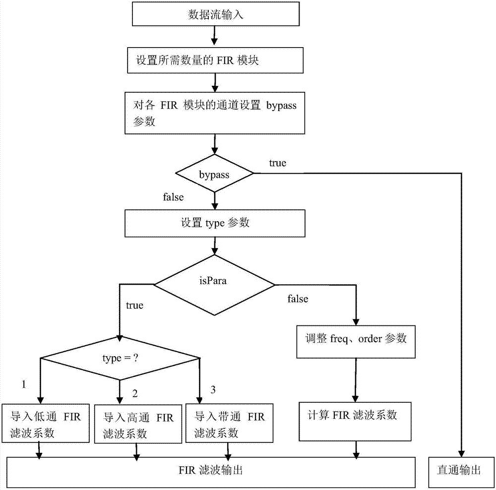
[0033] On the basis of Example 1, such as figure 2 As shown, the adjustment parameters include bypass, isPara, type, order, and freq parameters, and the frequency division processing method of the flexibly adjustable FIR audio digital frequency divider includes:
[0034] Step 101: Set the switch parameters of the routing module, turn on the required number of FIR modules, and perform the operations of steps 102-104 on each FIR module that is turned on;
[0035] Step 102: Set a bypass parameter for each FIR module that is turned on. When the bypass parameter is true, it means that the data stream does not need to be filtered and is output directly;
[0036] Step 103: When the bypass parameter is false, it means that the data stream needs to be filtered. First, set the type parameter identified as the desired filter type, and then set the isPara parameter. When the isPara parameter is true, it means that according to The set type coefficient is imported into the debugged FIR filter coefficient, and the data stream is filtered and output;
[0037] Step 104: When the isPara parameter is false, it means that the data stream does not directly import the debugged FIR filter coefficients, first set the freq parameter and the order parameter, calculate the filter coefficients, perform filtering processing, and finally output;
[0038] Step 105: The parameters set in the above steps 101-104 are transmitted to the routing module and each FIR module through the configuration unit, and each FIR module performs a straight-through output or a filtered output on the data stream.
[0039] Among them, bypass is the filter effective switch. When bypass is true, it means that the module does not need to be filtered, and false means that the module needs to be filtered; isPara is the switch control switch. When it is true, you can import the debugged FIR filter coefficients. Perform filter processing. When it is false, it means that the FIR filter coefficient can be calculated by adjusting the type parameter and the freq parameter to perform the filter processing; the type parameter is identified as the filter type, including low-pass, high-pass, and band-pass filtering; the freq parameter is the passband Cutoff frequency, the order parameter is the FIR filter order. With this technical solution, the number of channels, passband cutoff frequency and FIR of the FIR module of the FIR audio digital divider can be flexibly adjusted during use. The order of the filter can be adjusted, and you can also choose to directly import the adjusted FIR filter coefficients to better meet the user's different frequency division requirements. Further, the FIR module further includes a coefftable parameter, and the coefftable parameter is used to receive the FIR filter coefficients debugged in step 103.
[0040] The type parameter includes codes respectively identifying low-pass filters, high-pass filters and band-pass filters; the type parameters also include band-stop filters and multi-band-pass filters.
[0041] Such as figure 2 As shown, when type=1, it is identified as a low-pass filter. The flexibly adjustable FIR audio digital frequency divider imports low-pass FIR filter coefficients through the coefftable parameter to filter the data stream; when type=2 When type=3, it is marked as a high-pass filter. When type=3, it is marked as a band-pass filter.
[0042] At present, most of the frequency dividers divide the mid-band by using low-pass and high-pass filters in series. This solution uses band-pass filters to divide the mid-band. The benefits of this can save computing resources. For example, when performing a three-frequency division, the traditional frequency divider needs to perform two high-pass and low-pass filter processing respectively. This solution only needs to perform one high-pass, one low-pass, and one band-pass processing; while the high, low, and band-pass processing of the same order The calculation amount of the pass processing is equal. Therefore, this scheme saves one filter processing calculation when performing three-frequency division.
[0043] With this technical solution, users can freely combine different filter types according to needs, so that the flexibly adjustable FIR audio digital frequency divider achieves better processing effects, and can reduce the amount of calculation for filtering processing.

Example Embodiment

[0044] Example 3
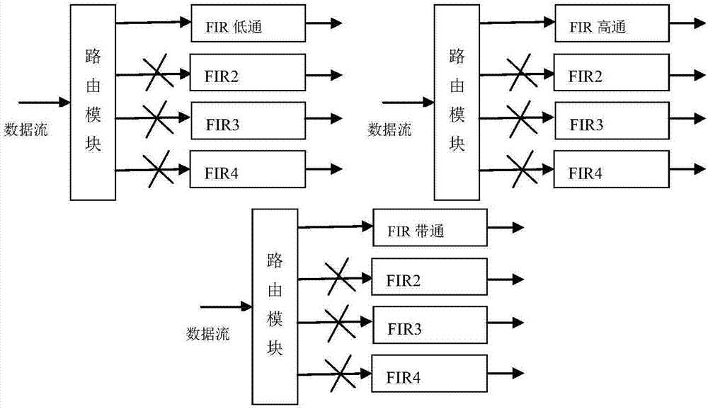
[0045] On the basis of Embodiment 2, the number of FIR modules is four. Using this technical solution, the flexibly adjustable FIR audio digital frequency divider can obtain single-channel filters, two-frequency, three-frequency and four-frequency filters (such as Figure 3-6 Shown, where Figure 4-6 For a partial list), the crossover effect is better.

PUM

no PUM

Description & Claims & Application Information

We can also present the details of the Description, Claims and Application information to help users get a comprehensive understanding of the technical details of the patent, such as background art, summary of invention, brief description of drawings, description of embodiments, and other original content. On the other hand, users can also determine the specific scope of protection of the technology through the list of claims; as well as understand the changes in the life cycle of the technology with the presentation of the patent timeline. Login to view more.

Similar technology patents

Body condition measuring device

InactiveUS20050234351A1simple structure
Owner:DENSO CORP

Magnetic cooling apparatus and control method thereof

ActiveUS20130180263A1simple structure
Owner:SAMSUNG ELECTRONICS CO LTD

Dual-Drivetrain of Power-Assist Vehicle

InactiveUS20100181130A1enhance uphill momentumsimple structure
Owner:CHOU WEN CHENG

Classification and recommendation of technical efficacy words

  • Simple structure
  • easy to operate

Sharing system for air-conditioning coat

InactiveCN107440179ASimple structureeasy to wear
Owner:QINGDAO HAIER AIR CONDITIONER GENERAL CORP LTD

Feeding device of sorter of batteries plate

InactiveCN101357717ASimple structurecooperate well
Owner:NANJING NORMAL UNIVERSITY

Emergency parachuting device and method for multiple-rotor unmanned aerial vehicle

InactiveCN103895870Aavoid aircraft crashSimple structure
Owner:SOUTH CHINA AGRI UNIV +1

Lancet device

InactiveUS7303573B2inexpensively mass-producedeasy to operate
Owner:ABBOTT DIABETES CARE INC

Rapid and non-invasive optical detection of internal bleeding

InactiveUS20050065436A1easy to operaterapid and accurate result
Owner:HO WINSTON ZONH +2
Why Eureka
Try Eureka