Optical backplane sub-frame device

A technology of optical backplane and rack device, applied in the direction of selection device, light guide, optics, etc., can solve the problems of large optical insertion loss and large optical switching card, and achieve the effect of improving integration, high capacity and reducing cost

Active Publication Date: 2017-07-14
ZTE CORP
View PDF5 Cites 13 Cited by
  • Summary
  • Abstract
  • Description
  • Claims
  • Application Information

AI Technical Summary

Problems solved by technology

[0006] In order to solve the above-mentioned problems, the present invention proposes an optical backplane subrack device, which overcomes the problem in the prior art that a 90° optical signal turning is required when connecting an optical backplane, resulting in large optical insertion loss, and directly connecting the line card and the switch card. Disadvantages of too large optical switching card due to vertical cross optical connection

Method used


Image

  • Optical backplane sub-frame device
  • Optical backplane sub-frame device
  • Optical backplane sub-frame device

Examples


Embodiment 1

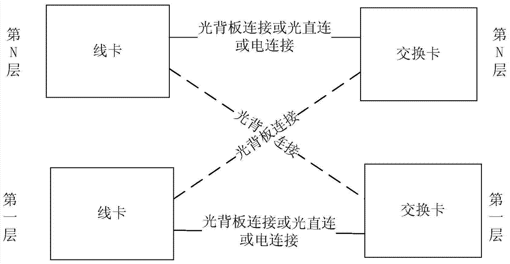
[0079] All line cards and switch cards are connected by optical paths, links on the same layer are directly connected through optical connections, and links on different layers are connected through optical backplanes.

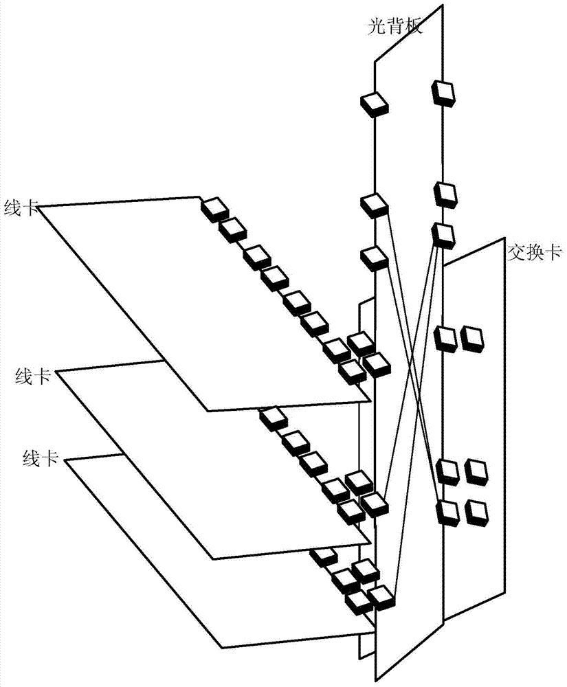
[0080] Such as figure 2 As shown in , one or more layers of switch cards are inserted vertically on the back of the subrack, and all line cards are inserted horizontally on the front. The optical backplane and the switch cards overlap in parallel. Links where line cards and switch cards are not on the same layer are connected through optical backplanes.

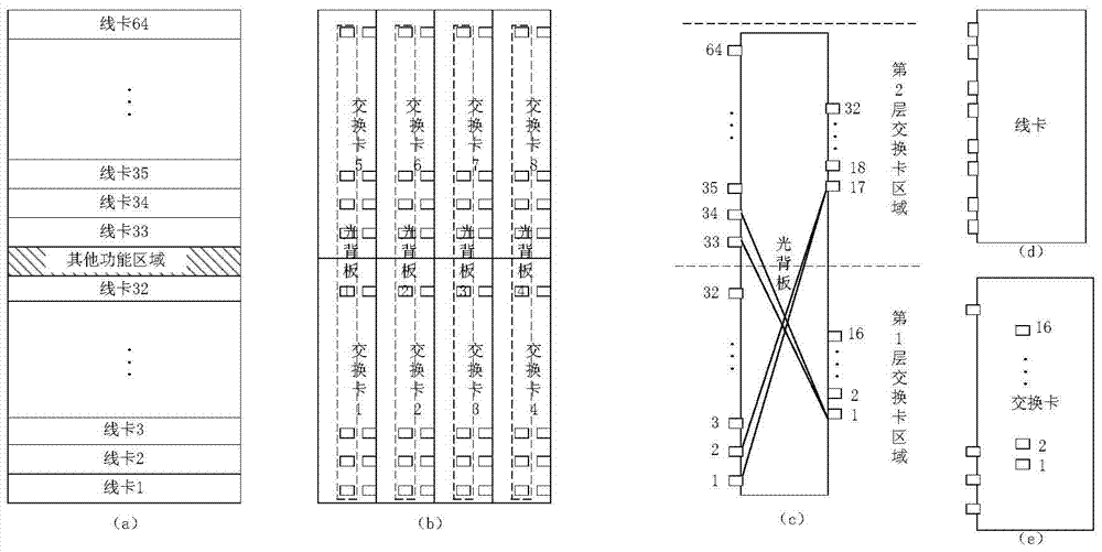
[0081] image 3 In the figure, take the subrack on the second floor as an example, a is the front of the subrack, all line cards are inserted horizontally, b is the back of the subrack, all switch cards are inserted vertically, and the dotted frame is the optical backplane, which is installed inside the switch card. It overlaps with the switch card in parallel, c is the optical backplane, d is the line car...

Embodiment 2

[0084] Line cards and switch cards are connected through optical hybrid, and links on the same layer are connected through electrical connectors ( Figure 4 The black connector in ) is directly connected, and the links of different layers pass through the optical backplane (the optical connector is Figure 4 middle white connector).

[0085] Such as Figure 4 As shown in , one or more layers of switch cards are inserted vertically on the back of the subrack, and all line cards are inserted horizontally on the front. The optical backplane and the switch cards overlap in parallel. Links where line cards and switch cards are not on the same layer are connected through optical backplanes.

[0086] Figure 5 In the case of a 2-layer subrack, 32 line cards are placed on the upper and lower layers of the front. The line cards have 8 connectors on the backplane side, of which 4 optical connectors are connected to 4 optical backplanes, and 4 are electrically connected to The connec...

Embodiment 3

[0089] All line cards and switch cards are optically connected through the optical backplane, and the optical backplane overlaps with the switch cards.

[0090] Such as Image 6 As shown in , one or more layers of switch cards are inserted vertically on the back of the subrack, and all line cards are inserted horizontally on the front. The optical backplane and the switch cards overlap in parallel. The optical backplane is connected.

[0091] Figure 7 In the case of a 2-layer subrack, 32 line cards are placed on the upper and lower layers of the front. The line cards have 4 optical connectors on the backplane side, and these 4 optical connectors are connected to 4 optical backplanes. There is a row of connectors on the switch card, and this row is an optical connector connected to the optical backplane in the board, which connects the line cards of all layers through the optical backplane. The optical backplane is also designed based on two layers. The two sides of the opt...


PUM


Abstract

The invention provides an optical backplane sub-frame device and relates to the field of communication. The device comprises one layer or more layers of sub-frames and P optical backplanes. Each layer of sub-frame comprises M switching cards and L line cards. Each switching card comprises one or more optical connectors or optical connectors and electric connectors. Each line card comprises one or more optical connectors or optical connectors and electric connectors. Two sides of each optical backplane comprise one or more optical connectors. The M switching cards of each layer are connected with all line cards of different layers through the optical connectors on the P optical backplanes, so at least one optical connection channel is arranged between all optical connectors corresponding to the line cards and all optical connectors corresponding to the switching cards located on different layers of sub-frames. The optical signal connection convenience is improved.

Description

technical field [0001] The present invention relates to OTN (Optical Transport Network, Optical Transport Network), PTN (Packet Transport Network, Packet Transport Network), routers and other communication devices that adopt Central Switch structure in the field of communication, in particular to an optical backlight Board rack device. Background technique [0002] With the increasingly strong demand for the Internet of Things and the rapid development of the Internet, a large number of services are transmitted between different sites in real time, which puts forward higher and higher requirements for the switching capacity of switching devices in the network. The centralized switching equipment based on OTN, PTN, and IP (Internet Protocol, Internet Protocol) mainly implements high-speed interconnection between service boards and switching boards through backplane wiring. [0003] At present, when optical backplane technology is used to realize high-speed interconnection of...

Claims


Application Information

Patent Timeline
Patent Type & Authority Applications(China)
IPC IPC(8): H04Q1/02G02B6/44
CPCG02B6/4452H04Q1/09H04Q1/155H04Q1/02
Inventor 尚迎春陈勋刘雨叶兵王会涛
Owner ZTE CORP
Why Eureka
Try Eureka