
Power tube driving system and method

A drive system and power tube technology, applied in the field of circuits, can solve problems such as the increase in the cost of electronic equipment, and achieve the effect of suppressing radiated electromagnetic interference

Active Publication Date: 2017-07-14
ON BRIGHT ELECTRONICS SHANGHAI
View PDF6 Cites 9 Cited by
  • Summary
  • Abstract
  • Description
  • Claims
  • Application Information

AI Technical Summary

Problems solved by technology

However, the use of inductors will increase the cost of electronic equipment, which should be avoided in the highly competitive consumer electronics market

Method used


Image

  • Power tube driving system and method
  • Power tube driving system and method
  • Power tube driving system and method

Examples


Embodiment Construction

[0015] Example embodiments will now be described more fully with reference to the accompanying drawings. Example embodiments may, however, be embodied in many forms and should not be construed as limited to the embodiments set forth herein; rather, these embodiments are provided so that this disclosure will be thorough and complete, and will fully convey the concept of example embodiments to those skilled in the art. In the drawings, the thicknesses of regions and layers may be exaggerated for clarity. The same reference numerals in the drawings denote the same or similar structures, and thus their detailed descriptions will be omitted.

[0016] Furthermore, the described features, structures, or characteristics may be combined in any suitable manner in one or more embodiments. In the following description, numerous specific details are provided in order to give a thorough understanding of embodiments of the invention. However, one skilled in the art will appreciate that th...


PUM


Abstract

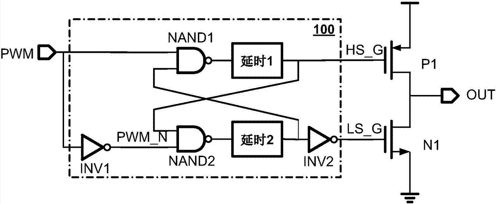
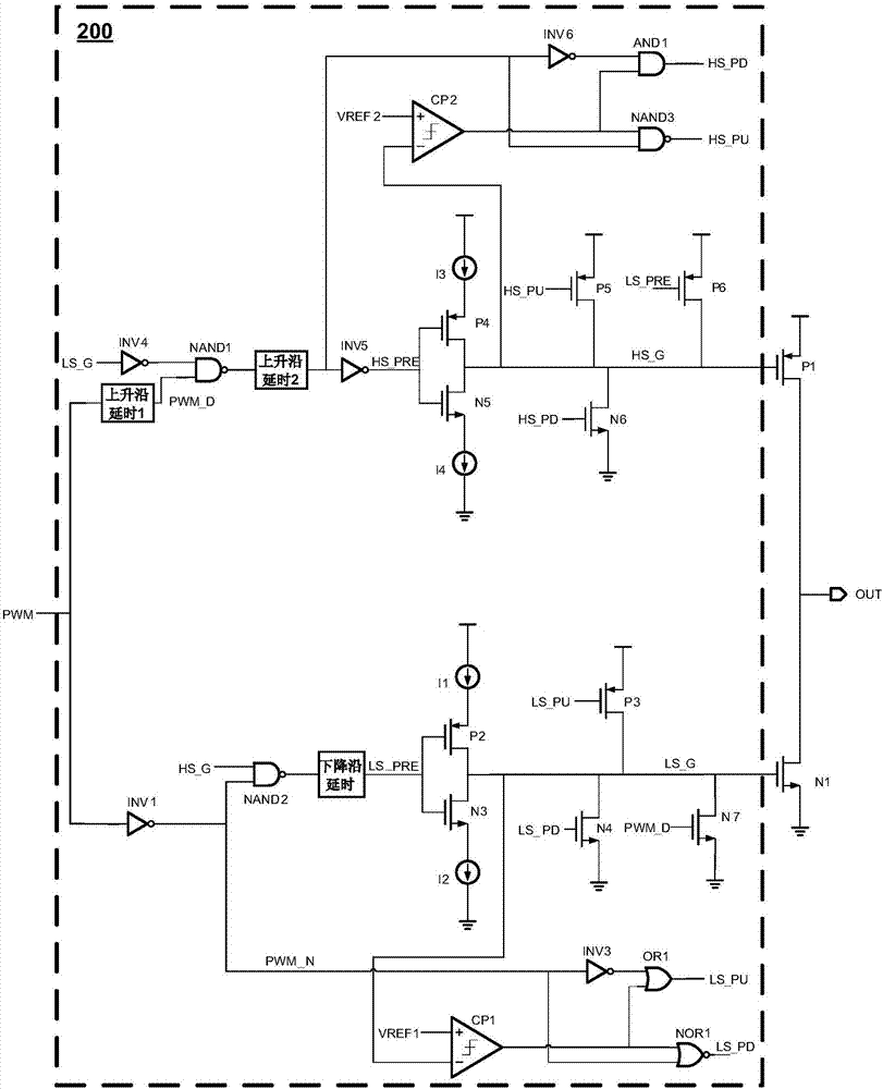
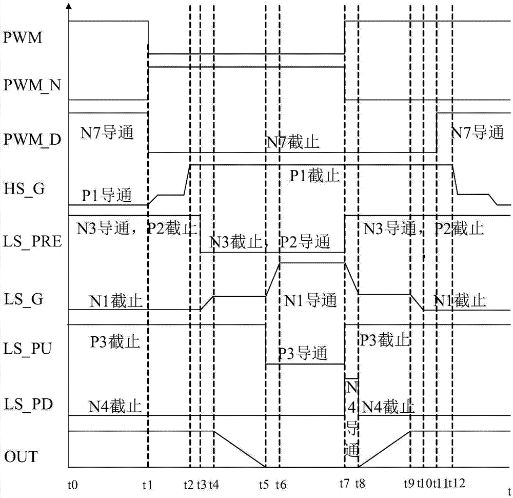
The invention provides a power tube driving system and method. The system comprises a driving circuit part of the lower tube of a power tube and a driving circuit part of the upper tube of the power tube. The driving circuit part of the lower tube of the power tube is configured to control the residence time of the lower tube of the power tube on a Miller platform by controlling the size of the first charging current for charging the stray capacitance of the lower tube of the power tube through a first switching circuit, and / or, control the residence time of the lower tube of the power tube on the Miller platform by controlling the size of the first discharging current for discharging the stray capacitance of the lower tube of the power tube through a second switching circuit. The driving circuit part of the upper tube of the power tube is configured to control the residence time of the upper tube of the power tube on the Miller platform by controlling the size of second discharging current for discharging the stray capacitance of the upper tube of the power tube through a third switching circuit, and / or, control the residence time of the upper tube of the power tube on the Miller platform by controlling the size of second charging current for charging the stray capacitance of the upper tube of the power tube through a fourth switching circuit.

Description

technical field [0001] The present invention relates to the circuit field, and more particularly relates to a power tube driving system and method. Background technique [0002] Today, the consumer electronics market requires electronic equipment to be lighter, smaller, and thinner while having more functions and more powerful, which requires higher and higher levels of circuit integration in electronic equipment. The continuous development of integrated circuit technology makes it possible to continuously increase the degree of circuit integration in electronic equipment. However, the increase in circuit integration in electronic equipment means that the chip and device density on the printed circuit board (PCB) in electronic equipment has increased, and the spacing between circuits has decreased, which has caused electromagnetic interference (EMI) in electronic equipment to become Outstanding issue. [0003] For example, Class D audio power amplifier has gradually become...

Claims


Application Information

Patent Timeline
Patent Type & Authority Applications(China)
IPC IPC(8): H04R3/00
CPCH04R3/00H04R2430/00
Inventor 顾全王冠男袁廷志方烈义
Owner ON BRIGHT ELECTRONICS SHANGHAI
Learn More