
Spinning dyeing and printing filtering device

A filter device and textile printing and dyeing technology, which is applied in the field of textile printing and dyeing, can solve the problems of inconvenient disassembly of the filter device, increase economic costs, and difficult maintenance, etc., and achieve the effects of easy movement, avoiding leakage, and preventing falling off

Inactive Publication Date: 2017-07-18
湖州梦源环保科技有限公司
View PDF1 Cites 4 Cited by
  • Summary
  • Abstract
  • Description
  • Claims
  • Application Information

AI Technical Summary

Problems solved by technology

[0003] The purpose of the present invention is to provide a filter device for textile printing and dyeing, which has the advantages of convenient disassembly of the filter device, easy maintenance, and reduced economic costs, and solves the problems of inconvenient disassembly of the filter device, difficulty in maintenance, and increased economic costs

Method used


Image

  • Spinning dyeing and printing filtering device
  • Spinning dyeing and printing filtering device
  • Spinning dyeing and printing filtering device

Examples


Embodiment Construction

[0017] The following will clearly and completely describe the technical solutions in the embodiments of the present invention with reference to the accompanying drawings in the embodiments of the present invention. Obviously, the described embodiments are only some, not all, embodiments of the present invention. Based on the embodiments of the present invention, all other embodiments obtained by persons of ordinary skill in the art without making creative efforts belong to the protection scope of the present invention.

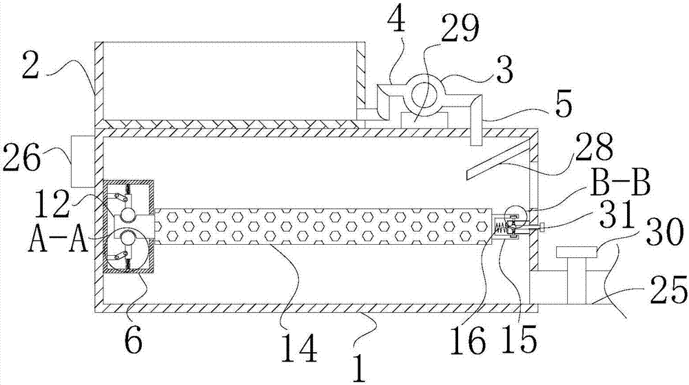
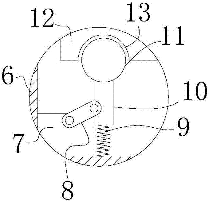
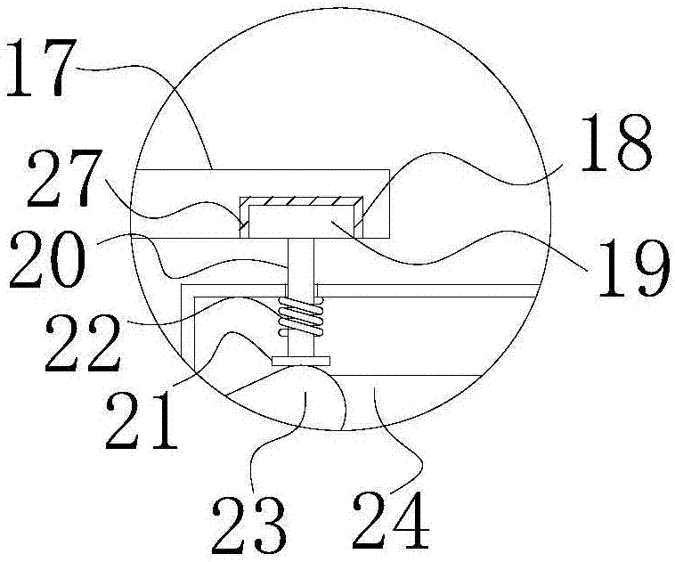
[0018] see Figure 1-3 , a textile printing and dyeing filter device, including a filter tank 1, the top of the right side of the filter tank 1 is fixedly connected with a slant plate 28, and the end of the slant plate 28 away from the inner wall of the filter tank 1 extends to the bottom of the first water outlet pipe 5, and passes through the slant plate The setting of 28 facilitates the flow of waste water to the filter screen 14, avoiding spillage, the rig...


PUM


Abstract

The invention discloses a spinning dyeing and printing filtering device which comprises a filtering tank, wherein a cloth dyeing tank is fixedly connected with the left side of the top of the filtering tank; a water pump is arranged at the top of the filtering tank; the water inlet of the water pump is communicated with a water inlet tube; one end far away from the water inlet of the water pump, of the water inlet tube is communicated with the right side of the cloth dyeing tank; a first water outlet tube is communicated with the water outlet of the water pump; one end far away from the water outlet, of the first water outlet tube, penetrates through the filtering tank and extends into the filtering tank; a fixing frame is fixedly connected with the middle of the left side of the inner cavity of the filtering tank; first adjusting rods are fixedly connected with two ends of the left side of the inner cavity of the fixing frame. Due to arrangement of a pull rod, an effect of driving a separation ball to move is achieved; due to arrangement of a third spring, an effect of driving a moveable rod to move is achieved; due to arrangement of a second groove, an effect of fixing a clamping block is achieved, and meanwhile problems that a filtering device is inconvenient to disassemble, hard to repair and high in economic cost are solved.

Description

technical field [0001] The invention relates to the technical field of textile printing and dyeing, in particular to a textile printing and dyeing filter device. Background technique [0002] Because textile printing and dyeing wastewater contains a large amount of short fiber yarn, if there is no slag removal equipment or the slag removal equipment is poor, it is easy for most of the waste yarn and other dirty things in the wastewater to enter the sewer, causing blockage and affecting people's health. In daily life, as the Chinese patent discloses "filtering device for textile printing and dyeing" (patent number: 201220472627.3), this patent has a simple structure and is easy to use. It can be poured out and then cleaned without direct contact with hands. It is clean and hygienic, and has good social and economic benefits. Once the filter device is damaged, it is difficult to repair due to inconvenient disassembly, which increases economic costs. Contents of the invention...

Claims


Application Information

Patent Timeline
Patent Type & Authority Applications(China)
IPC IPC(8): D06B23/14D06B23/20B01D29/03B01D29/60
CPCD06B23/14B01D29/03B01D29/60D06B23/20
Inventor 沈少华
Owner 湖州梦源环保科技有限公司
Learn More