Installation and positioning method of super-deep and large-diameter steel pipe columns

A technology for installation and positioning of steel pipe columns, applied in construction, foundation structure engineering, sheet pile walls, etc., can solve the problems of affecting bearing capacity, high construction cost, and long construction period, so as to reduce the possibility of broken piles and reduce hoisting The difficulty and the effect of simplifying the operation steps

Active Publication Date: 2019-01-29
中铁隧道局集团建设有限公司
View PDF6 Cites 0 Cited by
  • Summary
  • Abstract
  • Description
  • Claims
  • Application Information

AI Technical Summary

Problems solved by technology

[0003] At present, there are mainly the following methods for the installation of steel pipe columns in China: for the installation of shallow steel pipe columns, insert steel casings into the bored piles, and use hoisting equipment to hoist the steel pipe columns into the bored piles after pumping out the mud For the installation of deep-buried steel pipe columns, due to the low recovery rate of the steel casing and high construction costs, the mud retaining wall is retained for the bored piles, but the buoyancy generated by the mud in the bored piles is greater than that of the steel pipe during the hoisting of the steel pipe column. Due to the gravity of the column, the steel pipe column cannot sink, so it is necessary to add counterweight to the steel pipe column. In China, concrete is generally poured at the bottom of the steel pipe column to a certain height to increase the counterweight, and then the steel pipe column is hoisted into the bored pile with hoisting equipment; When installing ultra-deep steel pipe columns, the drilled piles must be installed with mud retaining wall to make the gravity of the steel pipe column greater than the buoyancy before installation. Due to the ultra-deep steel pipe column and large diameter, the added counterweight is large. If the steel pipe column is used to pour first Adding counterweight to concrete will inevitably lead to discontinuous pouring of steel pipe columns, which may break the pile, affect its bearing capacity and make hoisting difficult
[0004] At present, there are mainly the following methods for the positioning of steel pipe columns in China: for the positioning of shallow steel pipe columns, the locator is installed at the bottom of the artificial hole, the concrete is anchored and the locator is poured, and the position of the steel pipe column is adjusted to the design center. Disadvantages such as complicated procedures, long construction period, high safety risk, and poor positioning accuracy; for the positioning of deeply buried steel pipe columns, the domestic two-point positioning method of fixing the top of the steel pipe on the surface platform and positioning the lower part of the steel pipe with an underground screw jack is currently used in China. Find its center point, and then use the laser plummet to map vertically downwards. The distance between the laser point at the screw jack and the actual center point of the steel pipe is the offset distance, and then the operator goes down to the bottom of the steel pipe column to adjust the screw jack. Make the verticality of the steel pipe meet the design requirements. This positioning method requires the operator to go deep into the bottom of the steel pipe column to manually adjust the screw jack. The operating space is narrow, the construction speed is slow, and there is a certain safety risk; for the positioning of the ultra-deep steel pipe column, use In the above methods, it is necessary to manually go deep into the steel pipe column to adjust the positioning device, and the safety risk is extremely high.

Method used


Image

  • Installation and positioning method of super-deep and large-diameter steel pipe columns
  • Installation and positioning method of super-deep and large-diameter steel pipe columns
  • Installation and positioning method of super-deep and large-diameter steel pipe columns

Examples


Embodiment Construction

[0033] The present invention will be further described in detail below in conjunction with the accompanying drawings, so that those skilled in the art can implement it with reference to the description.

[0034] It should be noted that, in the description of the present invention, the terms "horizontal", "vertical", "upper", "lower", "front", "rear", "left", "right", "vertical", The orientation or positional relationship indicated by "horizontal", "top", "bottom", "inner", "outer", etc. is based on the orientation or positional relationship shown in the drawings, and is only for the convenience of describing the present invention and simplifying the description, and It is not to indicate or imply that the device or element referred to must have a particular orientation, be constructed in a particular orientation, or operate in a particular orientation, and thus should not be construed as limiting the invention.

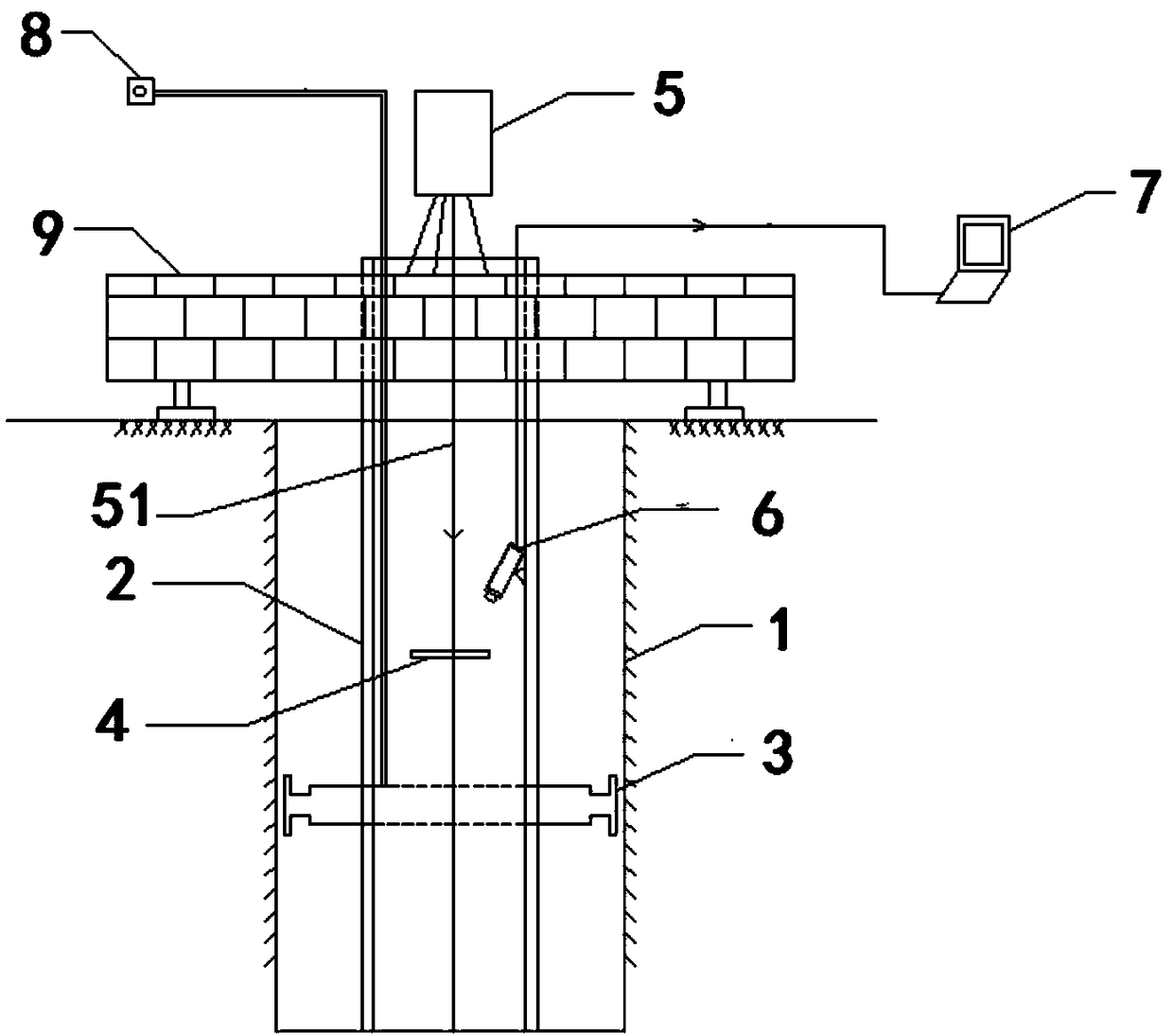
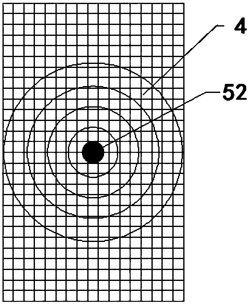
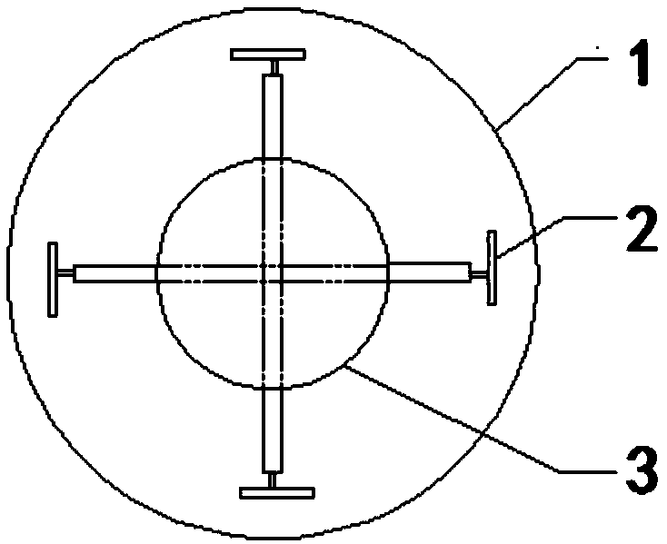
[0035] Such as Figure 1-Figure 3 As shown, the present inventi...


PUM


Abstract

The invention discloses a mounting positioning method of an ultra-deep large-diameter steel pipe column. The method comprises the following steps: step 1, calculating water filling height in the steel pipe column; step 2, arranging four jacks at the lower part of the steel pipe column, and horizontally mounting a positioning plate in the steel pipe column; step 3, vertically hoisting the steel pipe column to a designed position in a cast-in--situ pile, wherein water is gradually added to the steel pipe column during the hoisting until the water filling height calculated in step 1; and arranging a laser plummet of which laser beams are overlapped with a designed axis of a cast-in-situ bored pile on the top part of the steel pipe column; and step 4, determining the offset of the steel pipe column according to the position relation of the laser beams and a positioning plate; calibrating the position of the steel pipe column through the four jacks; and then enabling telescoping rods of the four jacks to be against the inner wall of a bored hole of the cast-in-situ bored pile after calibrating, thus finishing the positioning of the steel pipe column. The method is simple to operate, low in safety risk, and high in mounting and positioning accuracy; in addition, the visualized mounting and positioning construction of the steel pipe column is achieved.

Description

technical field [0001] The invention relates to the field of underground engineering construction. More specifically, the present invention relates to an installation and positioning method for an ultra-deep and large-diameter steel pipe column. Background technique [0002] Steel pipe columns are widely used in load-bearing structures such as subway stations due to their high bearing capacity, good plasticity and toughness, and convenient construction. However, the installation and positioning of steel pipe columns has become a technical problem in engineering. [0003] At present, there are mainly the following methods for the installation of steel pipe columns in China: for the installation of shallow steel pipe columns, insert steel casings into the bored piles, and use hoisting equipment to hoist the steel pipe columns into the bored piles after pumping out the mud For the installation of deep-buried steel pipe columns, due to the low recovery rate of the steel casing ...

Claims


Application Information

Patent Timeline
Patent Type & Authority Patents(China)
IPC IPC(8): E02D7/00
CPCE02D7/00
Inventor 莫智彪王炳华王升平林锐崔红利艾厚军刘进友兰廷波黎高辉石海良李强王军团张玉龙覃祚崇范育辉姜冲
Owner 中铁隧道局集团建设有限公司
Why Eureka
Try Eureka