Heat engine based on shape memory alloy driving

A memory alloy and drive mechanism technology, applied in the direction of mechanisms, machines/engines, and mechanical equipment that generate mechanical power. Energy cost, waste reduction effect

Inactive Publication Date: 2017-07-18
WUHAN UNIV OF SCI & TECH
View PDF7 Cites 7 Cited by
  • Summary
  • Abstract
  • Description
  • Claims
  • Application Information

AI Technical Summary

Problems solved by technology

[0003] It can be seen that industrial waste heat resources are very rich and widely exist in the production process of various industries. However, at present, my country's energy utilization still has problems such as low utilization efficiency, poor economic benefits, and high pressure on the ecological environment. "The policy requirements for energy conservation and emission reduction clearly stated in the plan are contrary to

Method used


Image

  • Heat engine based on shape memory alloy driving
  • Heat engine based on shape memory alloy driving
  • Heat engine based on shape memory alloy driving

Examples


Embodiment Construction

[0025] The technical scheme and working principle of the present invention will be described in detail below in conjunction with the drawings and embodiments.

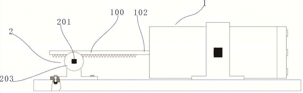
[0026] Such as figure 1 As shown, the heat engine driven by shape memory alloy includes a driving mechanism 1 and a transmission mechanism 2. The driving mechanism 1 drives the rack 100 to reciprocate through the push rod 10, so that the rack 100 drives the transmission shaft 201 of the transmission mechanism 2 to rotate. .

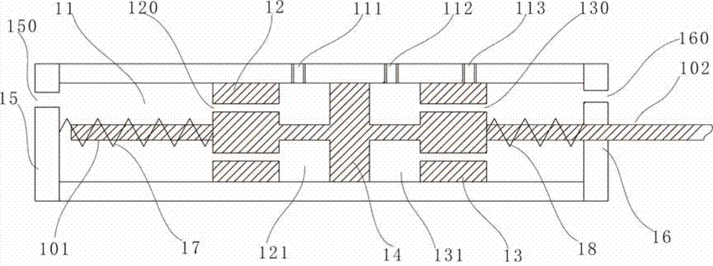
[0027] Such as figure 2 As shown, the driving mechanism 1 includes a hollow valve cavity 11, a piston 14 sliding left and right along the inner wall of the valve cavity 11 is arranged in the valve cavity 1, and a push rod is fixed on the piston 14, specifically: a first push rod is respectively arranged on the left and right sides of the piston 14 101 and the second push rod 102, wherein the second push rod 102 passes through the right end cover of the valve chamber 1, that is, the second end c...


PUM


Abstract

The invention discloses a heat engine based on shape memory alloy driving. The heat engine comprises a drive mechanism and a transmission mechanism. The drive mechanism comprises a hollow valve cavity internally provided with a piston. A push rod is fixed to the piston and penetrates through an end cover of the valve cavity to be matched with the end cover in a sliding mode. The push rod is driven by a shape memory alloy driving part located in the valve cavity. The valve cavity wall is provided with a heat inlet and a cold inlet which are used for making the shape memory alloy driving part deform. The transmission mechanism comprises a gear and a transmission shaft. A gear meshes with a rack. The rack is connected with the push rod and is matched with the gear. The gear and the transmission shaft are coaxial. The heat engine can convert heat energy into useful work, and environmental protection is facilitated.

Description

technical field [0001] The invention belongs to the technical field of power machinery, and in particular designs a driving heat engine which converts thermal energy into mechanical energy by using a shape memory alloy. Background technique [0002] As one of the most common renewable energy sources, thermal energy is difficult to apply on a large scale and has low efficiency in reality, especially for the utilization of thermal energy generated by small-scale biomass power generation and solar thermal energy. Directly evacuate a large amount of industrial waste heat, most of which are below 200°C. For example: waste heat of high-temperature flue gas in the building materials industry, waste heat of high-temperature products and slag in the machinery industry, chemical reaction heat in the chemical industry, and air, water and oil to protect high-temperature production equipment or meet the cooling requirements of the process The waste heat taken away by the cooling medium,...

Claims


Application Information

Patent Timeline
Patent Type & Authority Applications(China)
IPC IPC(8): F03G7/06
CPCF03G7/065
Inventor 朱学彪郑华生卢云丹李昭刘琥铖邓江红
Owner WUHAN UNIV OF SCI & TECH
Why Eureka
Try Eureka