Oil returning cooling structure of electro-hydraulic servo valve

An electro-hydraulic servo valve and servo valve technology, applied in the field of electro-hydraulic servo, can solve problems such as increased leakage, decreased magnetic permeability of soft magnetic materials, and jamming, so as to improve stability and life, reduce working environment temperature, and guarantee Achieving and Safe Effects

Pending Publication Date: 2017-07-18
SHANGHAI HENGTUO HYDRAULIC CONTROL TECH
View PDF0 Cites 0 Cited by
  • Summary
  • Abstract
  • Description
  • Claims
  • Application Information

AI Technical Summary

Problems solved by technology

When the ambient temperature changes, the sliding pair gap between the servo valve slide valves will change, which will easily cause wear, stagnation, jamming or increased leakage between the valve sleeve and valve core; the viscosity of the oil will change with the change of oil temperature , The throttling effect at the valve opening produces temperature rise, resulting in uneven temperature distribution in the valve, local heating in

Method used


Image

  • Oil returning cooling structure of electro-hydraulic servo valve
  • Oil returning cooling structure of electro-hydraulic servo valve
  • Oil returning cooling structure of electro-hydraulic servo valve

Examples


Example Embodiment

[0024] The present invention will be further described below in conjunction with the drawings and embodiments.

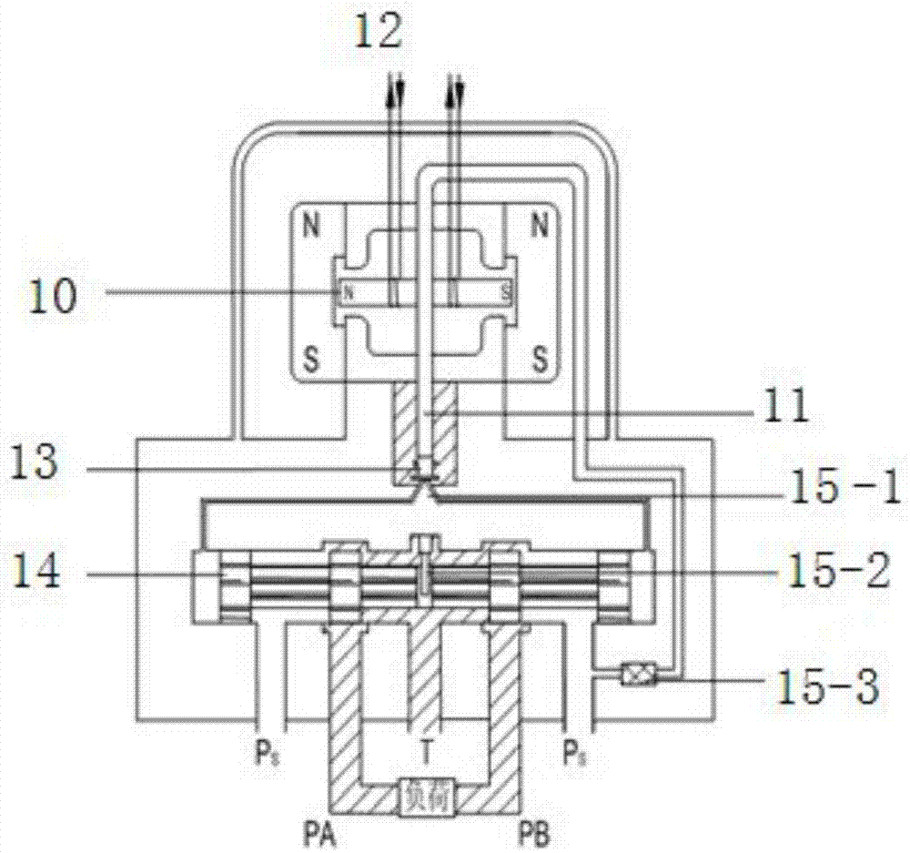
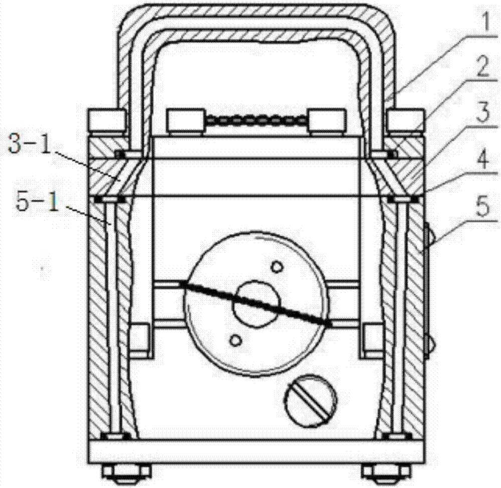
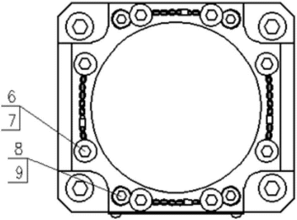
[0025] Such as Figure 2 to Figure 8 As shown, an oil return cooling structure of an electro-hydraulic servo valve includes a bushing 1, an upper cover 3, and a servo valve body 5. The servo valve body 5 is provided with a through hole on both sides of the oil inlet cavity and the oil return cavity. 5-1. The upper end of the servo valve body 5 is sealed and fixedly connected to the upper cover 3, and the upper cover 3 is sealed and fixedly connected to the bushing 1, and the bushing and the upper cover are overlapped and installed to form a cavity, which passes through the outer circle of the upper cover 3. The oblique holes 3-1 on both sides and the inlet cavity of the servo valve body 5 and the through holes 5-1 on both sides of the servo valve body 5 communicate with the inlet and return chambers of the servo valve body 5 to form the external flow passage of the ser...


PUM

PropertyMeasurementUnit
Diameteraaaaaaaaaa
The inside diameter ofaaaaaaaaaa
Outer diameteraaaaaaaaaa

Abstract

The invention relates to an oil returning cooling structure of an electro-hydraulic servo valve. The oil returning cooling structure of the electro-hydraulic servo valve is characterized in that a through hole is formed in each of two sides of an oil feeding chamber and an oil returning chamber of a servo valve body, wherein the upper end of the servo valve body is fixedly connected with an upper cover in a sealing manner, and a bushing is fixedly connected to the upper surface of the upper cover in the sealing manner; the bushing and the upper cover are mounted in an overlapping manner to form a storing chamber; the storing chamber communicates with the oil feeding chamber and the oil returning chamber of the servo valve body through inclined holes in two sides of an outer circle of the upper cover and the through holes in the two sides of the oil feeding chamber and the oil returning chamber of the servo valve body, thus forming an outer flowing channel and storing chamber cooling and oil returning structure of the servo valve; normal-temperature oil can be charged and circulated for cooling through the structure, thus the working environmental temperature of the servo valve can be decreased, and as a result, the stability and the service life of the servo valve can be improved and prolonged. With the adoption of the oil returning cooling structure, the electro-hydraulic servo valve can independently perform oil returning and cooling under a high-temperature environment; an independent cooling and oil returning channel is added in the servo valve, and the normal-temperature oil is charged and circulated for cooling, so that the working environmental temperature of a motor and the heated temperature of the materials of valve body and a slide valve can be effectively decreased, and as a result, the working environmental temperature of the servo valve is extremely decreased, and the stability and the service life of the servo valve can be improved and prolonged.

Description

technical field [0001] The invention relates to an electro-hydraulic servo in hydraulic engineering, in particular to an oil return cooling structure for an electro-hydraulic servo valve. Background technique [0002] The principle of electro-hydraulic servo valve is as follows: figure 1 As shown, it is mainly composed of torque motor, hydraulic amplifier, slide valve assembly and feedback assembly. The torque motor adopts a permanent magnet structure, the spring tube supports the jet tube 11 assembly of the armature 10, and isolates the motor from the hydraulic part, and the pre-stage is a hydraulic amplifier. Its working principle is: when the motor coil 12 inputs the control current, the control flux generated on the armature 10 interacts with the permanent magnet flux, so a torque is generated on the armature 10, causing the armature 10 to deflect a small angle proportional to the torque. Through the jet action of the nozzle 13, the pressure at one end of the spool 14 ...

Claims


Application Information

Patent Timeline
IPC IPC(8): F16K49/00
CPCF16K49/00
Inventor 程雪飞云霞张宪金瑶兰王思民
Owner SHANGHAI HENGTUO HYDRAULIC CONTROL TECH
Why Eureka
Try Eureka