Water discharging device and cooling fan
A cooling fan and water tank technology, which is applied in the field of sewage installations and cooling fans, can solve the problems of reducing the market competitiveness of products, increasing the cost of parts, loud noise, etc., and achieving the effects of reducing noise, reducing noise from launching, and reducing noise.
- Summary
- Abstract
- Description
- Claims
- Application Information
AI Technical Summary
Problems solved by technology
Method used
Image

Examples
Embodiment 1
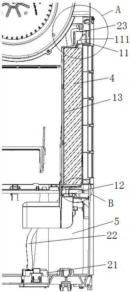
[0062] This embodiment provides a water launching device, which is used in a cooling fan. Specifically, such as image 3 with Figure 4 As shown, the sewer device in this embodiment includes a first sewer tank 11 for diverting the outlet water of the water pump pipeline in the cooling fan to the wet curtain. Wherein, the top of the first sink 11 is provided with a first water inlet, and the bottom is provided with a first discharge port 115 . The sewer device also includes a diversion structure 111, at least part of the diversion structure 111 is arranged in the first sewer tank 11 (here, the diversion structure 111 can be completely arranged in the first sewer tank 11, and can also be partially arranged in the first lower gutter. In the water tank 11. It depends on the position of the water outlet of the water pump pipeline. If the position of the water outlet of the water pump pipeline is higher than the first water inlet of the first lower tank 11, then part of the divers...
Embodiment 2
[0066] Preferably, this embodiment provides a water launching device, compared with the previous embodiment, such as Figure 4 As shown, the diversion structure 111 in this embodiment has an inclined surface 112, which is used to make the outlet water of the water pump pipeline in the cooling fan fall directly onto the inclined surface 112, and flow along the inclined surface 112 to the first sink 11 Inside. Through the above arrangement, the outlet water of the water pump pipeline in the cooling fan flows into the first water tank 11 along the inclined surface, further reducing the noise of the water in the cooling fan.
[0067] Preferably, the range of the angle α between the inclined surface 112 and the horizontal plane in this embodiment is: 30°≤α≤75°. Preferably, the range of the angle α between the inclined surface 112 and the horizontal plane is 53.8°. By setting the inclination of the inclined surface (that is, the angle with the horizontal plane) to the above-mentio...
Embodiment 3
[0069] Preferably, this embodiment provides a water launching device. Compared with Embodiment 2, the water launching device in this embodiment further designs the first water tank to further reduce the water launching noise in the cooling fan. The specific design is as follows :
[0070] Such as image 3 with Figure 4 As shown, the bottom of the first sink 11 includes a first bottom 114 and a second bottom 113 . Wherein, the first water outlet 115 is opened on the first groove bottom 114 . The second groove bottom 113 is higher than the first groove bottom 114; By setting like this, it is convenient to lower the water level and make water flow into the wet curtain; loud noise. Wherein, the flow guide structure 111 is disposed on the second groove bottom 113 . Moreover, the upper part of the inclined surface 112 is located close to the first water inlet, and the lower part of the inclined surface is located on the first groove bottom 114 . Preferably, the height differe...
PUM
 Abstract
Description
Claims
Application Information
 - R&D
- Intellectual Property
- Life Sciences
- Materials
- Tech Scout
- Unparalleled Data Quality
- Higher Quality Content
- 60% Fewer Hallucinations
Browse by: Latest US Patents, China's latest patents, Technical Efficacy Thesaurus, Application Domain, Technology Topic, Popular Technical Reports.
© 2025 PatSnap. All rights reserved.Legal|Privacy policy|Modern Slavery Act Transparency Statement|Sitemap|About US| Contact US: help@patsnap.com