
Concrete powring appts.

A pouring device and concrete technology, which is applied in shaft equipment, earthwork drilling, wellbore lining, etc., can solve the problems of damage, accelerated concrete falling speed, and low durability, and achieve the goals of preventing separation, reducing falling speed, and improving durability Effect

Inactive Publication Date: 2007-10-31
MAEDA CORPORATION
View PDF4 Cites 0 Cited by
  • Summary
  • Abstract
  • Description
  • Claims
  • Application Information

AI Technical Summary

Problems solved by technology

[0003] However, if the concrete is continuously moved from a high place, the falling speed of the concrete will increase, and the impact when it is put into the mixing device will increase.
Therefore, the mixing device has a problem of low durability due to wear and damage caused by the impact of concrete falling.

Method used


Image

  • Concrete powring appts.
  • Concrete powring appts.
  • Concrete powring appts.

Examples


Embodiment Construction

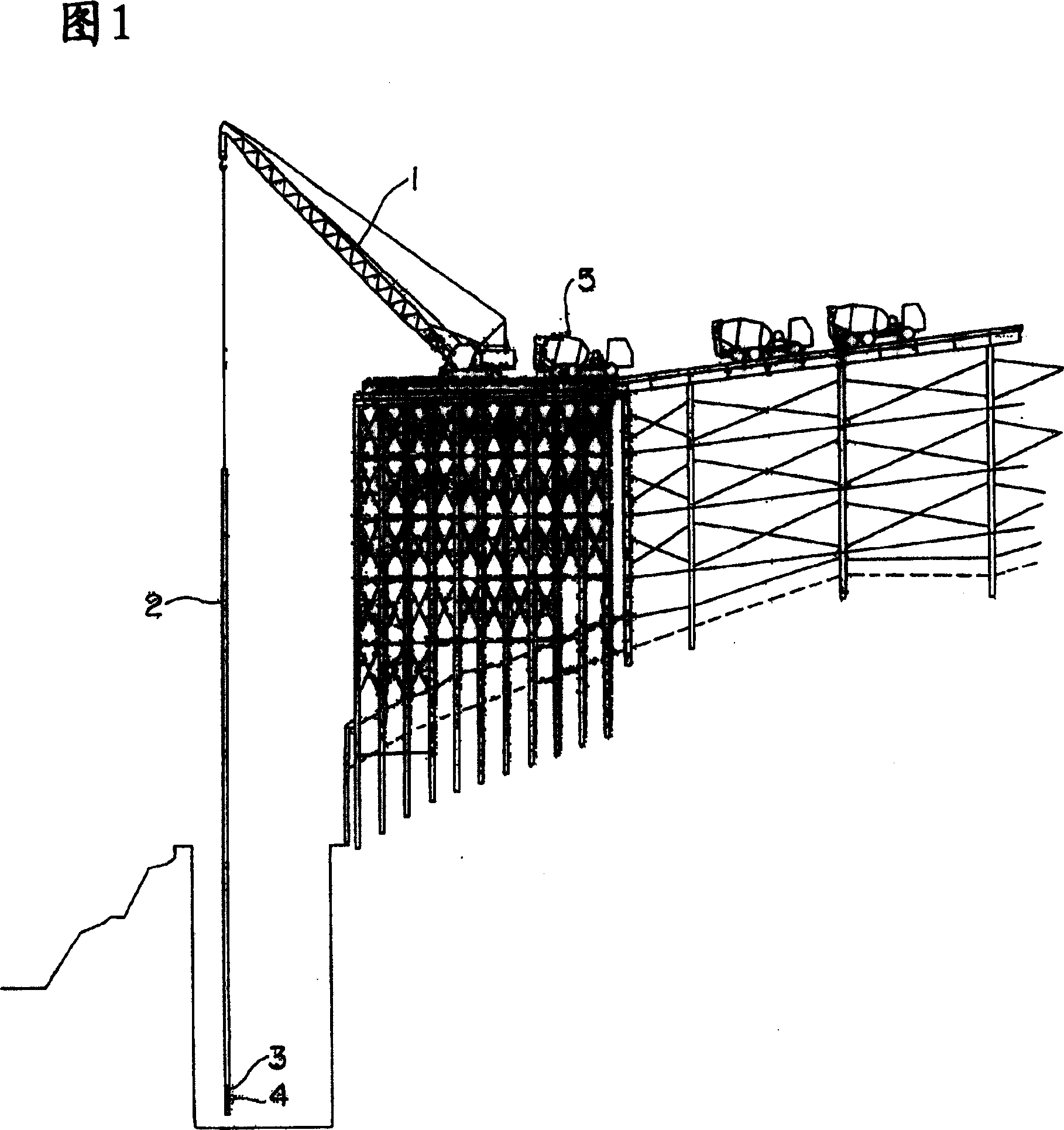
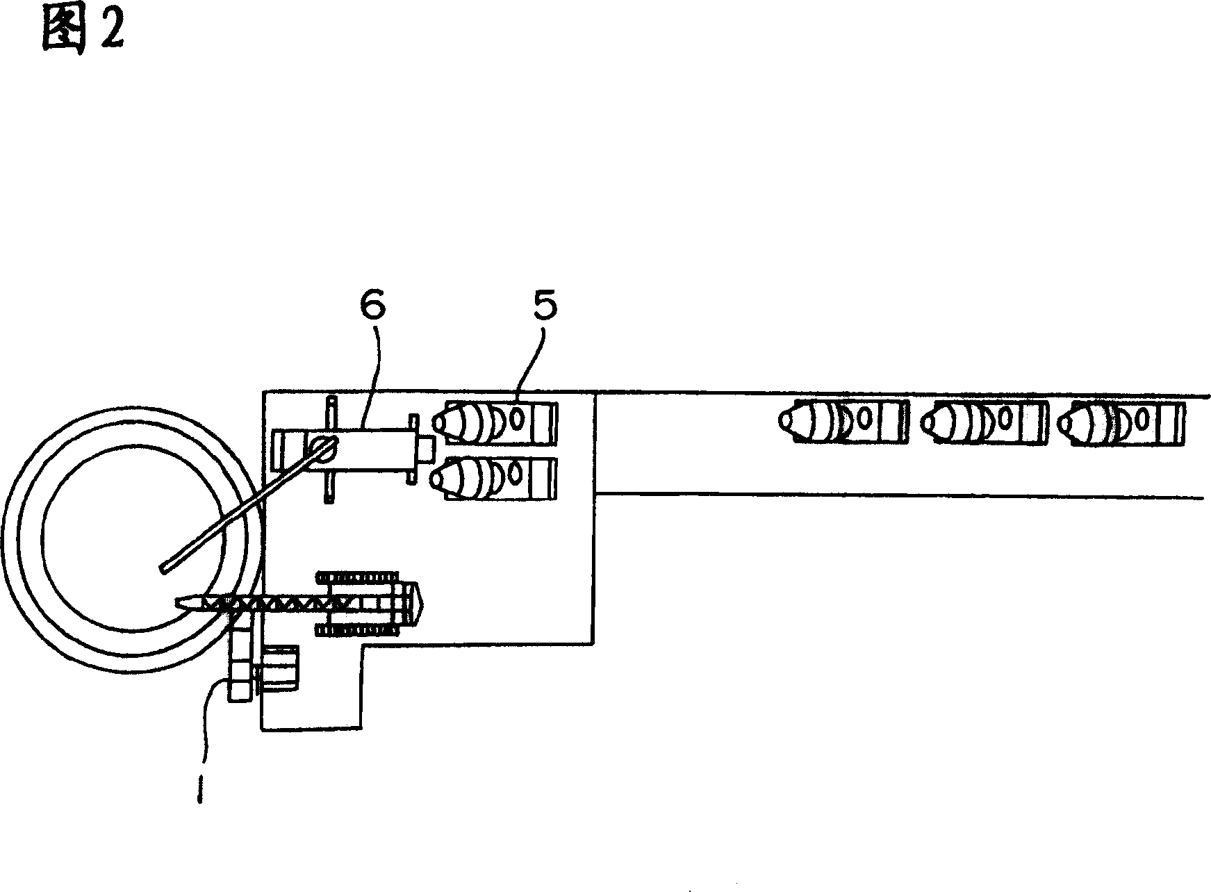
[0027] Hereinafter, embodiments of the concrete pouring device of the present invention will be described with reference to the drawings. 1 and 2 are schematic diagrams showing concrete pouring work according to an embodiment of the present invention. FIG. 1 is a side view, and FIG. 2 is a plan view. This embodiment is the concrete pouring operation in the bridge pier construction of the viaduct.

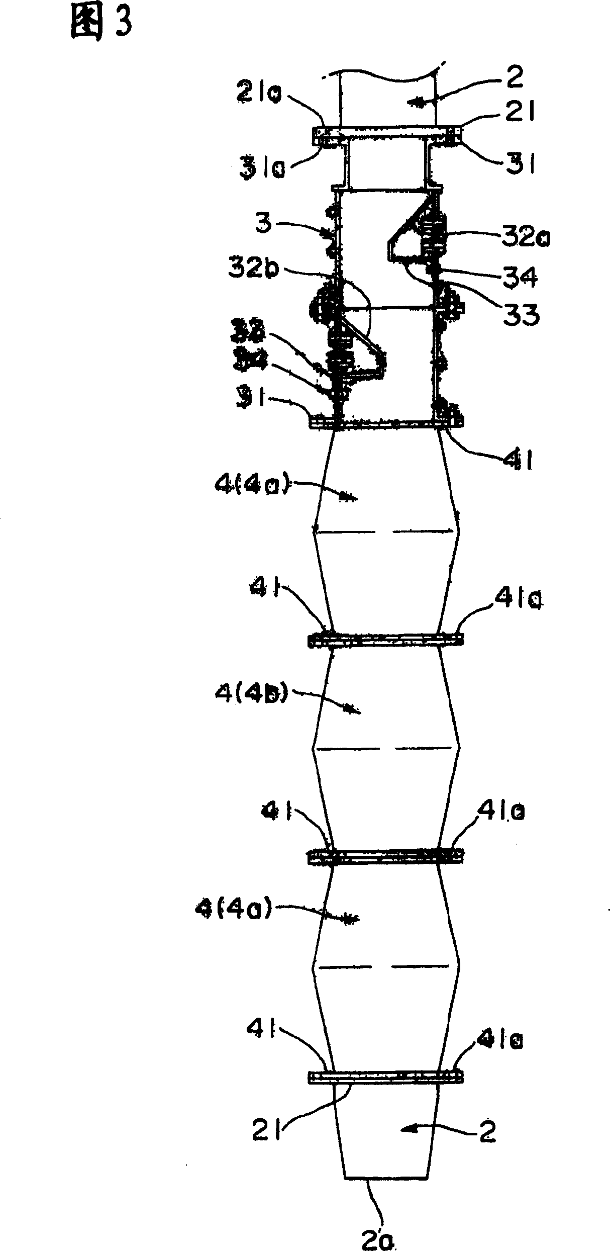
[0028] The concrete pouring device of the present embodiment is composed of a crawler crane 1 arranged on an erection work site arranged on a slope, a conveying pipe 2 suspended by the crawler crane 1 , a buffer device 3 connected below the conveying pipe 2 , and the The lower part of the buffer device 3 is connected to the stirring box 4. Moreover, the concrete mixer truck 5 and the concrete pump truck 6 are arrange|positioned adjacent to the crawler crane 1 mentioned above.

[0029] Here, the so-called crawler crane 1 is a type of mobile crane that can move on land, and the cra...


PUM


Abstract

The concrete placing device is provided with a conveyance tube 2 dropping concrete in gravity and transferring it to a concrete placing spot, a mixing box 4 connected in the midst of the conveyance tube 2 and having a deformed passage varying the sectional shape of the concrete flowing down in the inside to mix it, to which a plurality of elements are connected, and a buffer device 3 installed above the mixing box 4 to reduce the falling speed of the concrete. The concrete mixed by the mixing box 4 is discharged from the conveyance tube 2 and placed.

Description

technical field [0001] The invention relates to a concrete pouring device, in particular to a technology capable of pouring concrete while preventing separation of aggregates when pouring concrete from a high position such as a dam embankment site, a bridge pier, or a shield tunnel site. Background technique [0002] Conventionally, when concrete is poured from a high place, a chute is installed from the high place to the concrete pouring site, and the concrete falls in the chute by its own weight. However, if the falling path of the concrete is extended, there is a problem that aggregates are separated in the concrete during the falling. For this reason, a stirring device for stirring concrete is provided in the middle of the chute, which is the falling path of the concrete, and when the concrete passes through the inside, the separated concrete is stirred again (for example, Japanese Patent Application Laid-Open No. 2000-96825 (pages 2-3, figure 1)). [0003] However, if...

Claims


Application Information

Patent Timeline
Patent Type & Authority Patents(China)
IPC IPC(8): E04G21/02E02B7/00E01D19/02E21D11/10E04G21/04
CPCE04G21/04
Inventor 篠田佳男宮田雅章
Owner MAEDA CORPORATION
Learn More