
Powder laying precision compensation system and powder laying precision compensation method used for rapid forming equipment

A technology of forming equipment and precision compensation, applied in the direction of using feedback control, improving process efficiency, additive manufacturing, etc., can solve problems such as precision decline and bearing clearance, and achieve the goal of reducing calibration, avoiding tilt deformation, and improving motion accuracy. Effect

Active Publication Date: 2017-07-18
西安赛隆增材技术股份有限公司
View PDF3 Cites 0 Cited by
  • Summary
  • Abstract
  • Description
  • Claims
  • Application Information

AI Technical Summary

Problems solved by technology

[0003] When the existing powder spreading workbench performs reversing movement, due to the forward and reverse rotation of the motor in the powder spreading mechanism, the bearing in the powder spreading mechanism will have clearance, resulting in a decrease in accuracy

Method used


Image

  • Powder laying precision compensation system and powder laying precision compensation method used for rapid forming equipment
  • Powder laying precision compensation system and powder laying precision compensation method used for rapid forming equipment
  • Powder laying precision compensation system and powder laying precision compensation method used for rapid forming equipment

Examples


Embodiment Construction

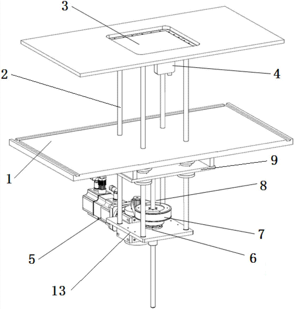
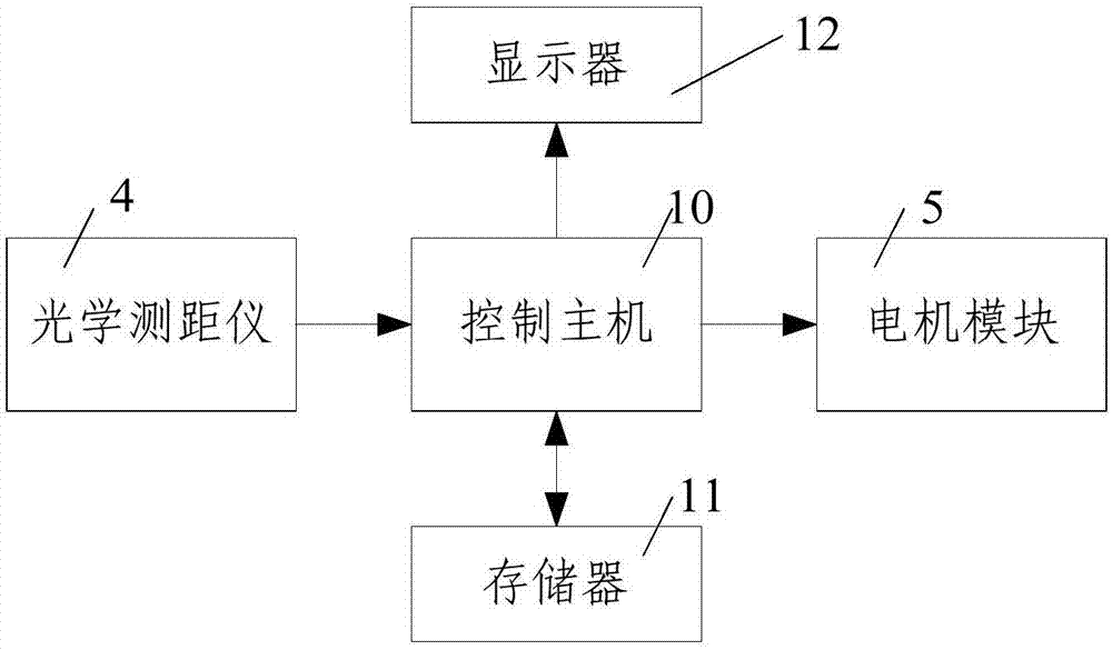
[0037] like figure 1 and figure 2 As shown, a powder spreading accuracy compensation system for rapid prototyping equipment according to the present invention includes a powder spreading device installed on the bottom plate 1 of the rapid prototyping equipment and a control host 10 for controlling and compensating the lifting of the powder spreading device The powder spreading device includes an optical axis 2 that vertically passes through the bottom plate 1 of the rapid prototyping equipment and is slidingly fitted with the bottom plate 1 of the rapid prototyping equipment, and a powder layer lift that is horizontally arranged on the top of the optical axis 2 and is used to lay a powder layer for the workpiece to be formed. The workbench 3 and the mounting plate 13 arranged at the bottom of the optical axis 2 and used to install the optical axis lifting drive mechanism, the optical axis lifting drive mechanism consists of a lead screw that passes through the mounting plate ...


PUM


Abstract

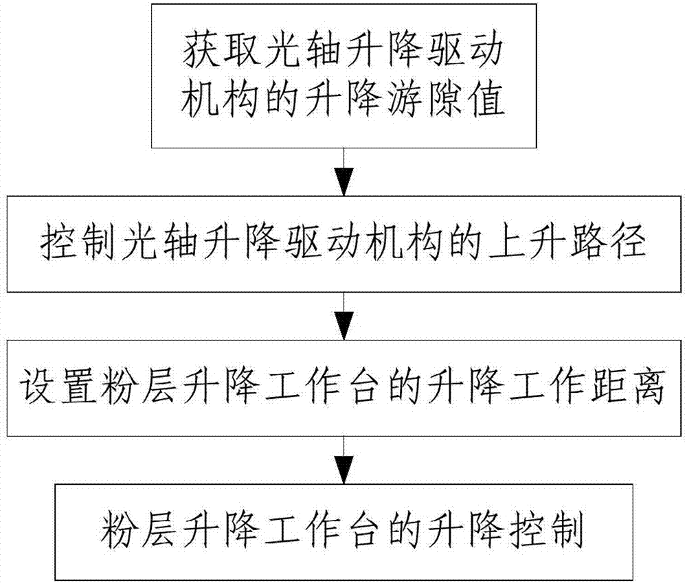
The invention discloses a powder laying precision compensation system and a powder laying precision compensation method used for rapid forming equipment. The powder laying precision compensation system comprises a powder laying device disposed on the bottom plate of the rapid forming equipment and a control host used for the control and the compensation of the elevating of the powder laying device. The powder laying device comprises an optical axis, a powder layer elevating working bench, and an installation plate used for installation of optical axis elevating driving mechanism. The powder laying precision compensation method comprises steps that 1, the elevating clearance value of the optical axis elevating driving mechanism is acquired; 2, the rising path of the optical axis elevating driving mechanism is controlled, 201, the rising of the optical axis elevating driving mechanism is initialized, 202, the rising of the optical axis elevating driving mechanism is compensated, 203, the falling of the optical axis elevating driving mechanism is calibrated; 3, the elevating working distance of the powder layer elevating working bench is set; 4, the elevating of the powder layer elevating working bench is controlled. The rising process of the optical axis elevating driving mechanism is ended by a falling state, and the calibration of the optical axis elevating driving mechanism from the rising state to the falling state is reduced, and the operation precision and the operation reliability of the powder layer elevating working bench are improved.

Description

technical field [0001] The invention belongs to the technical field of motion precision compensation of a powder spreading mechanism of rapid prototyping equipment, and in particular relates to a powder spreading precision compensation system and method for rapid prototyping equipment. Background technique [0002] In rapid prototyping technology, using powder as raw material, the rapid prototyping technology of parts through selective deposition / sintering / melting process is a hot spot in the field of rapid manufacturing. The existing selective sintering technology completes the processing of parts by layered scanning . During the processing, every time a layer is processed, the powder spreading workbench is lowered by a certain distance, the powder feeder sends out a certain amount of powder, and then the powder spreading mechanism flattens it, and then the layer of powder is sintered, and this process is repeated continuously. A process, and finally complete the processin...

Claims


Application Information

Patent Timeline
Patent Type & Authority Applications(China)
IPC IPC(8): G05D3/12B22F3/105B33Y30/00B33Y50/02
CPCG05D3/12B22F3/003B33Y30/00B33Y50/02B22F10/10B22F10/00B22F12/30B22F12/60B22F12/22B22F10/30B22F10/31B22F10/28Y02P10/25
Inventor 任龙贾文鹏赵培周勃延薛旭东向长淑汤慧萍
Owner 西安赛隆增材技术股份有限公司
Learn More