
a vibration sensor

A technology of vibration sensor and structural layer, which is applied in the field of sensors, can solve the problems of various wafer processing, high price, diaphragm vibration characteristics and strength influence, etc., and achieve the effect of increasing the sound of the sound, increasing the volume, and realizing the miniaturization

Active Publication Date: 2019-08-09
FOSHAN HEHONG TAIYE TECH CO LTD
View PDF5 Cites 0 Cited by
  • Summary
  • Abstract
  • Description
  • Claims
  • Application Information

AI Technical Summary

Problems solved by technology

However, in devices such as DRIE and ICP, the cost of the device is high and the processing of wafers varies, resulting in poor productivity.
[0005] In addition, there is also a method of performing crystal anisotropic etching on the semiconductor substrate from the surface side, but in this method, etching holes have to be opened on the diaphragm, and the etching holes will affect the vibration characteristics and vibration characteristics of the diaphragm as time goes by. strength, etc. cause adverse effects
[0006] However, in this etching method, when the substrate after etching the protective layer on the surface is etched, the thin film is exposed to the etchant of the substrate, so single crystal silicon or polycrystalline silicon cannot be used as the material of the thin film.
In addition, since the thin film is directly formed on the substrate, it is difficult to add processes and structures for controlling the stress of the thin film, improving the characteristics of the vibration sensor, etc.

Method used


Image

  • a vibration sensor

Examples


Embodiment Construction

[0031] The present invention will be further described in detail below in conjunction with the accompanying drawings and specific embodiments.

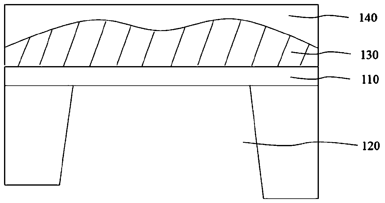
[0032] Such as figure 1 As shown, the technical solution adopted in the present invention is: a vibration sensor, the vibration sensor includes:

[0033] Monocrystalline silicon substrate 110;

[0034] a trapezoidal opening 120 formed on the lower surface of the single crystal silicon substrate 110, which is obtained by etching the lower surface of the single crystal silicon substrate 110;

[0035] The corrugated multilayer structure 130 formed on the upper surface of the single crystal silicon substrate 110 having the trapezoidal opening 120, the corrugated multilayer structure 130 includes at least one set of oppositely arranged structural layers, and the set of structural layers includes two structural layers, At least one of the two structural layers is corrugated;

[0036] An electrode layer 140 formed on the surface of the co...


PUM


Abstract

The invention provides a vibration sensor comprising a monocrystalline silicon substrate, a trapezoid opening, a corrugated multilayer structure and an electrode layer, wherein the trapezoid opening is formed in the lower surface of the monocrystalline silicon substrate by etching; the corrugated multilayer structure is formed on the upper surface of the monocrystalline silicon substrate with the trapezoid opening, and comprises at least one set of oppositely arranged structural layers, the set of structural layers comprises two structural layers, and at least one of the two structural layers is corrugated; the electrode layer is formed on the surface of the corrugated multilayer structure; and the at least one set of structural layers is configured to be able to have relative displacement under the effect of an external force to detect the vibration effect of the outside. According to the vibration sensor provided by the invention, miniaturization of the vibration sensor can be achieved, and furthermore, volume of the opening can be increased, so that the acoustic compliance of acoustic equipment can be increased when the vibration sensor is applied to an acoustic sensor.

Description

technical field [0001] The invention relates to the field of sensors, in particular to a vibration sensor. Background technique [0002] Currently, a vibration sensor in which a thin film is formed by laminating single crystal silicon or polycrystalline silicon on a silicon substrate and used as a diaphragm is being developed using semiconductor integrated circuit manufacturing technology. A diaphragm made of silicon has less internal stress and a lower density than metals such as aluminum or titanium, so a vibration sensor with high sensitivity can be obtained, and it has good compatibility with the manufacturing process of semiconductor integrated circuits. In the prior art condenser microphone, after a diaphragm (movable electrode) and a fixed electrode are formed on the surface of a semiconductor substrate made of a single crystal silicon surface, an etching mask is formed on the outer peripheral portion of the back surface of the semiconductor substrate, The semiconduc...

Claims


Application Information

Patent Timeline
Patent Type & Authority Patents(China)
IPC IPC(8): H04R9/06H04R9/02
CPCH04R9/02H04R9/06H04R2400/11
Inventor 甘立军
Owner FOSHAN HEHONG TAIYE TECH CO LTD
Learn More