
Flip-over electric ring apparatus

A circumcision device, electric technology, applied in surgical fixation nails, medical science, surgery and other directions, can solve problems such as timing and strength instability, incomplete nailing, U nails clipping the foreskin tissue, etc. Synchronization risk, mold opening and the effect of reduced production costs and a minimalist appearance

Pending Publication Date: 2017-07-21
WUHU SHANGRING TECH CO LTD
View PDF5 Cites 3 Cited by
  • Summary
  • Abstract
  • Description
  • Claims
  • Application Information

AI Technical Summary

Problems solved by technology

[0005] Thereupon the circumcision device has been developed in this field again, and the circumcision is sutured at one time using staples, but the circumcision devices in the prior art all adopt manual manual drive or remote pedal drive, and the manual drive itself The characteristics lead to great instability in the surgical operation, especially the timing and strength of the U nail. Excessive force may cause the U nail to pinch the foreskin tissue and cause the operation to fail, while too little force may cause incomplete nailing. As a result, the inability to stop the bleeding will also lead to the failure of the operation, and the use of manual drive also requires that the circumcision device itself has two sets of driving structures to drive the circumcision knife and the U nail respectively. Once the two sets of drive structures are inconsistent, the circumcision knife will be completed. Circumcision but the U-screw did not stop the bleeding at the same time, or the U-screw has been driven but the circumcision has not been completed, any of the above situations will cause great risks and pain for the patient

Method used


Image

  • Flip-over electric ring apparatus
  • Flip-over electric ring apparatus
  • Flip-over electric ring apparatus

Examples


Embodiment Construction

[0041] The present invention will be described in detail below according to the accompanying drawings, which is a preferred embodiment among various implementations of the present invention.

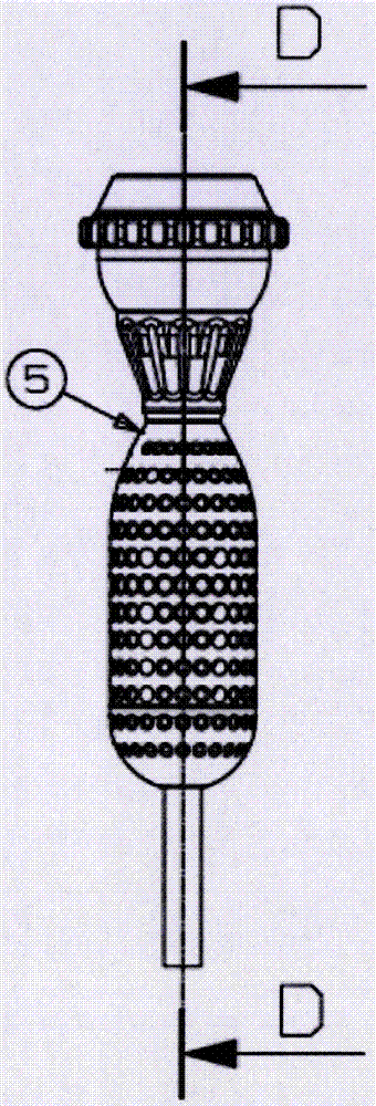
[0042] figure 1 and Figure 5 This is the overall view and perspective view of the outward-turning circumcision device. It can be seen that the overall appearance of the circumcision device driven by the motor is simple, and the device such as handle hinge is no longer used, and the mold opening and production costs are greatly reduced.

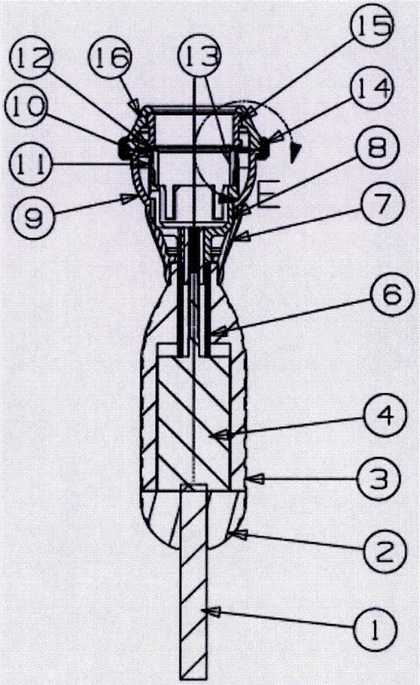
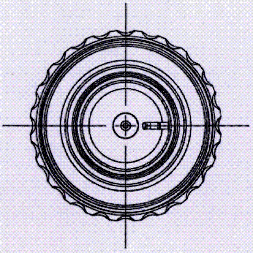
[0043] see figure 2 , 6, which are the structural diagram and partial enlarged diagram respectively. The structure in the figure includes cable 1, motor rear housing 2, motor front housing 3, motor 4, switch 5, push tube 6, integrated cover 7, U nail top ring 8, Lower cover 9, U nails 10, ring cutter 11, U nail backing ring 12, inner comprehensive cover 13, locking ring 14, inner ring 15, upper cover 16, and related driving parts, actuating parts and...


PUM


Abstract

The invention relates to a flip-over electric ring apparatus which comprises a motor, an ejector sleeve and a U nail top ring. The motor is connected to or makes contact with the ejector sleeve and is used for pushing the ejector sleeve forwards; the ejector sleeve is connected to or makes contact with the U nail top ring and is used for pushing the U nail top ring forwards. The motor is adopted for driving, pushing force to a U nail is adjustable and stable, the phenomenon that due to excessive force, the U nail clamps prepuce tissue to be broken, and then surgery fails is avoided, and meanwhile the phenomenon that due to too small force, nail reversing is not thorough, and then bleeding cannot be stopped can also be avoided, adjustment of the pushing distance and speed is conducted through a switch, and the flip-over electric ring apparatus can be adapted to different surgical objects and surgical environments; in addition, due to the fact that driving is conducted through the motor, a hand-operated driving device and an actuator structure do not need to be additionally arranged, and the asynchronous risk brought by two driving structures is avoided.

Description

technical field [0001] The invention relates to the field of circumcision, in particular to an eversion type electric circumcision device. Background technique [0002] Prepuce or phimosis is one of the root causes of male urinary tract infections as well as sexually transmitted diseases. Excessive prepuce or phimosis can cause urinary tract infection and lead to chronic prostatitis, back pain, impotence and premature ejaculation and a series of symptoms. Therefore, removing the prepuce is one of the best measures to prevent these diseases. [0003] Traditionally, surgical removal of phimosis or overlong foreskin is performed, and the key technical points are excision of excess foreskin, hemostasis, and suturing of the skin at the incision margin. The patient could not move around after the operation, and the pain was unbearable every time the medicine was changed, and he still had to endure great pain when the stitches were finally removed. In addition, incomplete ligation...

Claims


Application Information

Patent Timeline
IPC IPC(8): A61B17/326A61B17/068
CPCA61B17/0682A61B17/326A61B2017/00398A61B2017/00017
Inventor 商晶晶商建忠
Owner WUHU SHANGRING TECH CO LTD
Learn More