Concrete wet spraying machine

A technology of concrete and wet spraying machine, which is applied in the direction of spraying device, spraying device, earth drilling and mining, etc. It can solve the problems of unsatisfactory spraying effect, incomplete pipeline cleaning, inconvenient installation and disassembly, etc., to achieve good spraying effect and easy installation The effect of dismantling and avoiding pipe blockage

Pending Publication Date: 2017-07-21
河南省耿力工程设备有限公司
View PDF4 Cites 2 Cited by
  • Summary
  • Abstract
  • Description
  • Claims
  • Application Information

AI Technical Summary

Problems solved by technology

[0003] The existing concrete spraying machine has the following defects: 1. The connection of compressed air to the spray head is mainly realized by the cyclone, while the cyclone used in the existing spraying vehicle is not only inconvenient to install and disassemble, but also the injection pressure generated by it is relatively low , the spray effect is not ideal, and pipe blockage will occur, which will reduce the construction efficiency; 2. The conveying pipeline of the spraying truck needs to be cleaned after the work is completed to avoid concrete condensation on the inner wall of the pipeline, causing pipeline blockage
The cleaning method of the traditional concrete wet spraying machine is to continue to pass water in the delivery pipeline to flush out the residual concrete, but there will be defects such as incomplete cleaning of the pipeline, easy blockage of the pipeline, and unclean cleaning

Method used


Image

  • Concrete wet spraying machine
  • Concrete wet spraying machine
  • Concrete wet spraying machine

Examples


Embodiment Construction

[0030] The specific implementation manners of the present invention will be described in detail below in conjunction with the accompanying drawings.

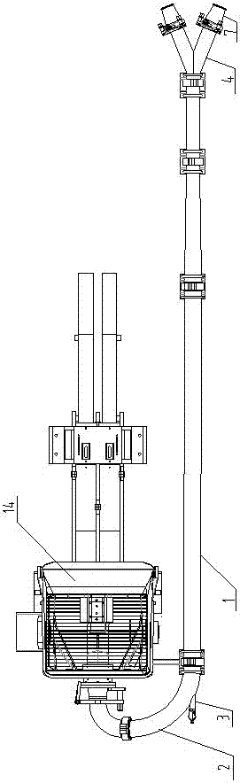
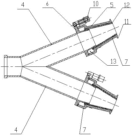
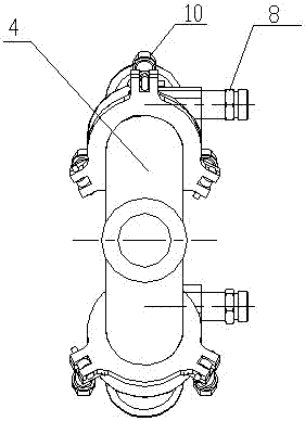
[0031] Such as Figure 1 to Figure 8 Shown, a kind of concrete wet spraying machine of the present invention, it comprises the pumping system 14 that is installed on the automobile chassis, the concrete conveying pipeline that is connected with pumping system 14 and the sprinkler 4 that is located at the concrete conveying pipeline outlet end, so The concrete conveying pipeline includes a conveying straight pipe 1 and a connecting elbow 2, the head joint of the connecting elbow 2 is connected with the pumping system, the tail joint of the connecting elbow 2 is connected with the conveying straight pipe 1, and the conveying straight pipe 1 is connected along the The extension line of the pipe body section where the tail joint of the connecting elbow 2 is located is coaxially arranged; the connecting elbow 2 is provided with a cle...


PUM


Abstract

The invention discloses a concrete wet spraying machine. The concrete wet spraying machine comprises a pumping system, a concrete conveying pipeline connected with the pumping system, and a spraying head arranged at the outlet end of the concrete conveying pipeline. The concrete conveying pipeline comprises a conveying straight pipe and a connecting bent pipe. The connecting bent pipe is provided with a cleaning air inlet pipe. The cleaning air inlet pipe communicates with the interior of a pipe body of the connecting bent pip in a sealed mode, and the air outlet direction of the cleaning air inlet pipe is arranged along the central axis of the conveying straight pipe. The cleaning air inlet pipe is externally connected with an air supply source. The spraying head is arranged at the outlet end of the conveying straight pipe and provided with a rotational flow structure, an installation structure and an air inlet structure. The rotational flow structure comprises a rotational flow head coaxially fixed to the front end of the spraying head. The installation structure comprises an annular installation plate. The air inlet structure comprises an air inlet sleeve arranged at the front end of the rotational flow head in a sleeving mode. According to the concrete wet spraying machine, the spraying effect is improved, and subsequently, the conveying pipeline is efficiently cleaned.

Description

technical field [0001] The invention relates to the technical field of concrete wet spraying, in particular to a concrete wet spraying machine. Background technique [0002] Wet concrete spraying machine is mainly used in engineering construction. Its basic principle is to use hydraulic pressure to transport the ready-mixed concrete to the nozzle through the pipeline, connect compressed air and concrete additives to the nozzle mouth, and then spray the concrete to the sprayed surface at high speed. The concrete support layer is formed after rapid setting and hardening. [0003] The existing concrete spraying machine has the following defects: 1. The connection of compressed air to the spray head is mainly realized by the cyclone, while the cyclone used in the existing spraying vehicle is not only inconvenient to install and disassemble, but also the injection pressure generated by it is relatively low , the injection effect is not ideal, and pipe blockage will occur, which ...

Claims


Application Information

Patent Timeline
IPC IPC(8): B08B9/032B05B7/04B05B1/34E21D11/10E02D15/00
CPCE21D11/10E02D15/00B05B1/341B05B7/0416B08B9/0328
Inventor 史宏冲宋志良孙伟
Owner 河南省耿力工程设备有限公司
Why Eureka
Try Eureka