Prefabricated concrete mold

A technology of prefabricated concrete and concrete, which is applied in the field of concrete pouring, can solve the problems of high cost and heavy workload, and achieve the effect of reducing workload, reducing cost, saving work steps and capital investment

Pending Publication Date: 2017-07-21
珠海筑享云科技有限公司
View PDF13 Cites 5 Cited by
  • Summary
  • Abstract
  • Description
  • Claims
  • Application Information

AI Technical Summary

Problems solved by technology

[0005] The purpose of the present invention is to provide a precast concrete mold to solve the technical problems of heavy workload during insta

Method used


Image

  • Prefabricated concrete mold
  • Prefabricated concrete mold
  • Prefabricated concrete mold

Examples


Embodiment Construction

[0038] It should be noted that, in the case of no conflict, the embodiments of the present invention and the features in the embodiments can be combined with each other. The present invention will be described in detail below with reference to the accompanying drawings and examples.

[0039] In the description of the present invention, it should be noted that unless otherwise specified and limited, the terms "installation", "connection" and "connection" should be understood in a broad sense, for example, it can be a fixed connection or a detachable connection. Connected, or integrally connected; it can be mechanically connected or electrically connected; it can be directly connected or indirectly connected through an intermediary, and it can be the internal communication of two components. Those of ordinary skill in the art can understand the specific meanings of the above terms in the present invention in specific situations.

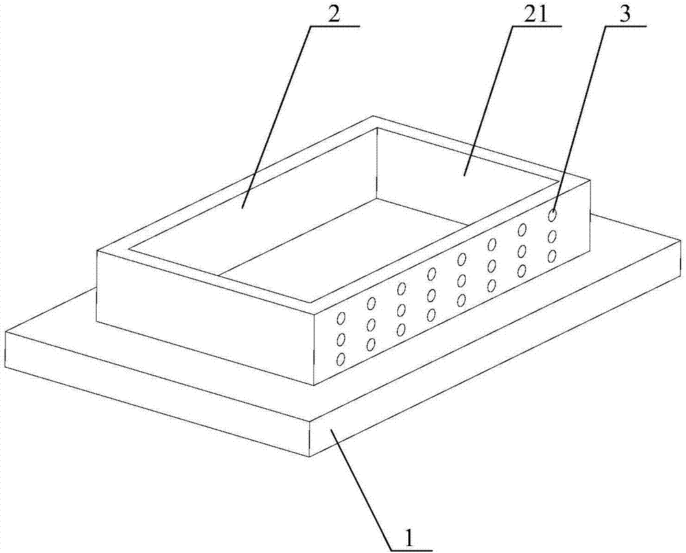
[0040] figure 1 is a schematic structural view...


PUM


Abstract

The invention relates to the technical field of concrete pouring, in particular to a prefabricated concrete mold. The prefabricated concrete mold comprises a bottom mold and a side mold detachably arranged on the bottom mold. The mold has three working states comprising a preparation state, a distribution state and a mold removal state. In the mold removal state, a solidified concrete prefabricated component is separated from the bottom mold and transferred, the side mold is further provided with multiple overflow through holes, and therefore concrete can overflow from the overflow through holes and is solidified outside the side mold to form protrusions. Due to the arrangement of the overflow through holes, concrete in the side mold can overflow and form the protrusions, the concrete component and the side mold are integrated for use, the side mold does not need to be removed from the component, the working step of mounting and demounting the side mold is omitted, and the workload is reduced. Meanwhile, the roughness of the exterior of the side mold is increased due to the protrusions outside the side mold, the face with the protrusions is an exposed face, and the working step and investment for processing and manufacturing the exposed face are omitted, and the cost is reduced.

Description

technical field [0001] The invention relates to the technical field of concrete pouring, in particular to a prefabricated concrete mold. Background technique [0002] Precast concrete molds are prefabricated molds used to pour concrete. The mold includes a bottom mold and a ring-shaped side mold. The side formwork is detachably arranged on the bottom formwork, the shape of the cavity surrounded by the side formwork and the bottom formwork is flat, and the concrete components manufactured by it are plate-type components. The side forms are provided with through-holes for inserting reinforcing bars. The mold has three working states: preparation state, cloth state and demoulding state. In the preparation state, the bottom form is placed on the bottom, and the side forms are placed on the bottom form to form a closed loop; in the laying state, the concrete is poured and enriched to form a closed loop formed by the side forms; in the demoulding state, the solidified concrete ...

Claims


Application Information

Patent Timeline
IPC IPC(8): B28B7/00
CPCB28B7/0002B28B7/0014B28B7/0029B28B7/0055
Inventor 徐鑫贾海云
Owner 珠海筑享云科技有限公司
Why Eureka
Try Eureka