Ceramic edge cutting machine with automatic correction device

An automatic correction and correction device technology, which is applied in the direction of grinding/polishing safety devices, machine tools suitable for grinding the edge of workpieces, manufacturing tools, etc., can solve the problem of inability to ensure the squareness of tiles, the inability to effectively reduce diagonal errors, and damage to tiles And other issues

Active Publication Date: 2017-07-21
GUANGDONG SINID TECH
View PDF7 Cites 6 Cited by
  • Summary
  • Abstract
  • Description
  • Claims
  • Application Information

AI Technical Summary

Problems solved by technology

However, the existing correction device is to set two correction blocks on the left and right sides of the tile conveyor belt, and the tile conveyor belt needs to be stopped, and then the centering correction is performed from the left and right sides of the tiles, and only one tile can be corrected at a time , the correction efficiency is low; the two correction blocks will squeeze the tiles during correction, which is easy to cause damage to the tiles; and it cannot effectively reduce the diagonal error during edge trimming, and cannot ensure that the tiles after edge trimming are square, which gives The processing of square tiles brings trouble; there is also the existing calibration device that needs to adjust the distance between the two calibration blocks according to the size of the tiles, which has low production flexibility and adaptability

Method used


Image

  • Ceramic edge cutting machine with automatic correction device
  • Ceramic edge cutting machine with automatic correction device
  • Ceramic edge cutting machine with automatic correction device

Examples


Embodiment Construction

[0043] The technical solutions of the present invention will be further described below in conjunction with the accompanying drawings and through specific implementation methods.

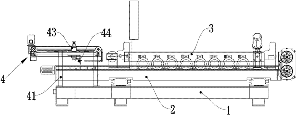
[0044] The ceramic trimming machine with automatic correction device of the present embodiment, such as figure 1 As shown, it includes a base 1, a feeding conveyor belt 2 and at least two trimming devices 3, the feeding conveyor belt 2 is installed on the base 1, and at least two of the trimming devices 3 are symmetrically arranged on the The left and right sides of the above-mentioned feeding conveyor belt 2;

[0045] It also includes a correction device 4, the correction device 4 is installed on the base 1 and arranged on the upstream section of the feeding conveyor belt 2, and the trimming device 3 is arranged on the downstream section of the feeding conveyor belt 2 ;

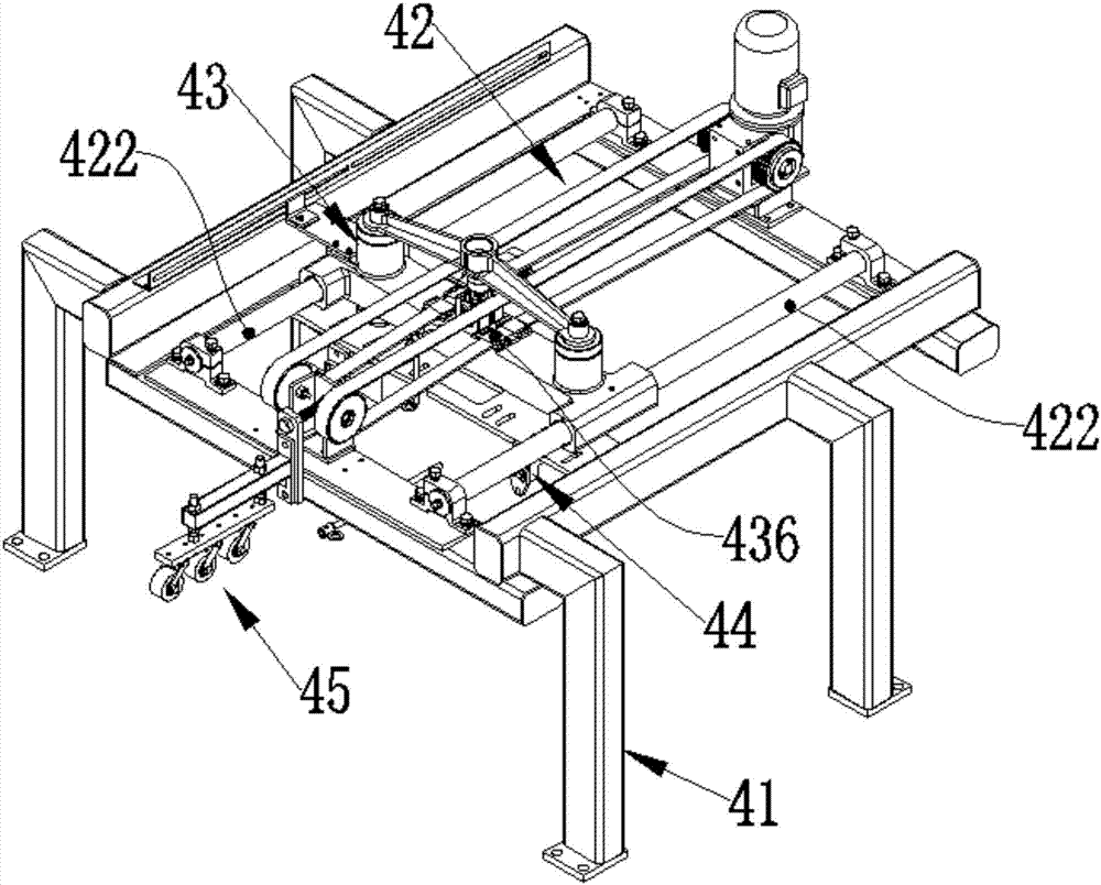
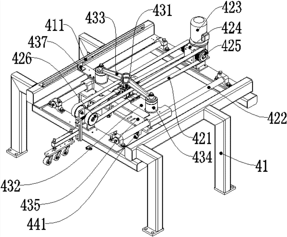
[0046] The correction device 4 includes a synchronous sliding unit 42, a brick pushing activity unit 43 and a correction block...


PUM


Abstract

The invention discloses a ceramic edge cutting machine with an automatic correction device. The ceramic edge cutting machine comprises a base, a feeding conveying belt and at least two edge cutting devices. The ceramic edge cutting machine further comprises the correction device. The correction device comprises a synchronous sliding unit, a tile pushing movement unit and a correction block unit. A sliding drive module drives a sliding drive belt to rotate, and the sliding drive belt drives a tile pushing sliding base to slide horizontally. According to the ceramic edge cutting machine with the automatic correction device, ceramic tiles can be corrected before an edge cutting working procedure is executed, and therefore diagonal errors of the tiles are lowered, the cutting precision is improved, the effect that the four edges of the ceramic tiles produced after edge cutting are upright and foursquare is guaranteed, the ceramic tiles in the conveying process can be corrected, dynamic correction can be realized, correction efficiency is improved, and losses of the feeding conveying belt by frequent brake stopping and restarting are reduced.

Description

technical field [0001] The invention relates to the field of building ceramic production equipment, in particular to a ceramic edge trimmer with an automatic correction device. Background technique [0002] After the tiles are processed, there are burrs all around, which cannot meet the specified size requirements and precision, so the burrs must be removed first, which requires a tile edge trimmer to trim the tiles. In order to improve the edge trimming accuracy, a correction device is usually installed at the input end of the tile edge trimmer, so that the edge of the tile and the sliding track of the cutter are parallel to each other. However, the existing correction device is to set two correction blocks on the left and right sides of the tile conveyor belt respectively. The tile conveyor belt needs to be stopped, and then the centering correction is performed from the left and right sides of the tiles, and only one tile can be corrected at a time. , the correction effi...

Claims


Application Information

Patent Timeline
Patent Type & Authority Applications(China)
IPC IPC(8): B28D1/00B28D1/24B28D7/04B28D7/00B24B9/06B24B27/00B24B41/00B24B41/06B24B55/00
CPCB24B9/06B24B27/0076B24B41/005B24B41/06B24B55/00B28D1/003B28D1/24B28D7/00B28D7/005B28D7/04
Inventor 杨扬叶金伟李松
Owner GUANGDONG SINID TECH
Why Eureka
Try Eureka