Revolution sprayer assembly for 3D printer

A technology of 3D printers and nozzle components, applied in the field of 3D printing, can solve the problems of affecting printing efficiency and increasing the complexity of programming, and achieve the effect of simplifying the programming process and shortening the printing time

Pending Publication Date: 2017-07-21
ANHUI TECHN COLLEGE OF MECHANICAL & ELECTRICAL ENG
View PDF6 Cites 10 Cited by
  • Summary
  • Abstract
  • Description
  • Claims
  • Application Information

AI Technical Summary

Problems solved by technology

The 3D printing model in the prior art sometimes contains some symmetrical elements, and even the whole model is a symmetrical structure. When printing this kind of three-dimensional model, the nozzle prints a section and repeats the same path several times, which not only affects printing efficiency, but also And it will increase the complexity of programming to a certain extent

Method used


Image

  • Revolution sprayer assembly for 3D printer
  • Revolution sprayer assembly for 3D printer
  • Revolution sprayer assembly for 3D printer

Examples


Embodiment 1

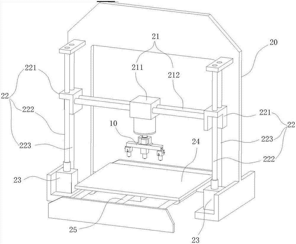
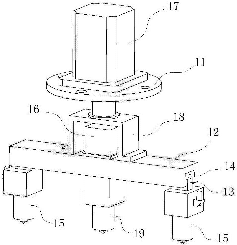
[0017] Such as figure 1 , 2 , 3, a 3D printer includes a rotary nozzle assembly 10, the rotary nozzle assembly 10 includes a connecting portion 11 and a rotary portion 12, the connecting portion 11 is used to connect the nozzle 15 driving mechanism of the rotary nozzle assembly of the 3D printer , the turning part 12 is rotatably arranged on the connecting part 11 along the vertical axis, and at least two sliders 13 are arranged on the turning part 12, and each slider 13 moves along a circle centered on the turning center of the turning part 12. The radial direction of the shaped area is slidably arranged on the rotary part 12, and each slider 13 is set for synchronous and symmetrical movement with the center of rotation of the rotary part 12 as a symmetrical point; a nozzle 15 is installed on each slider 13, and The position of each spray head 15 is arranged symmetrically with respect to the center of rotation of the rotation part 12 . The rotary nozzle assembly of the 3D p...

Embodiment 2

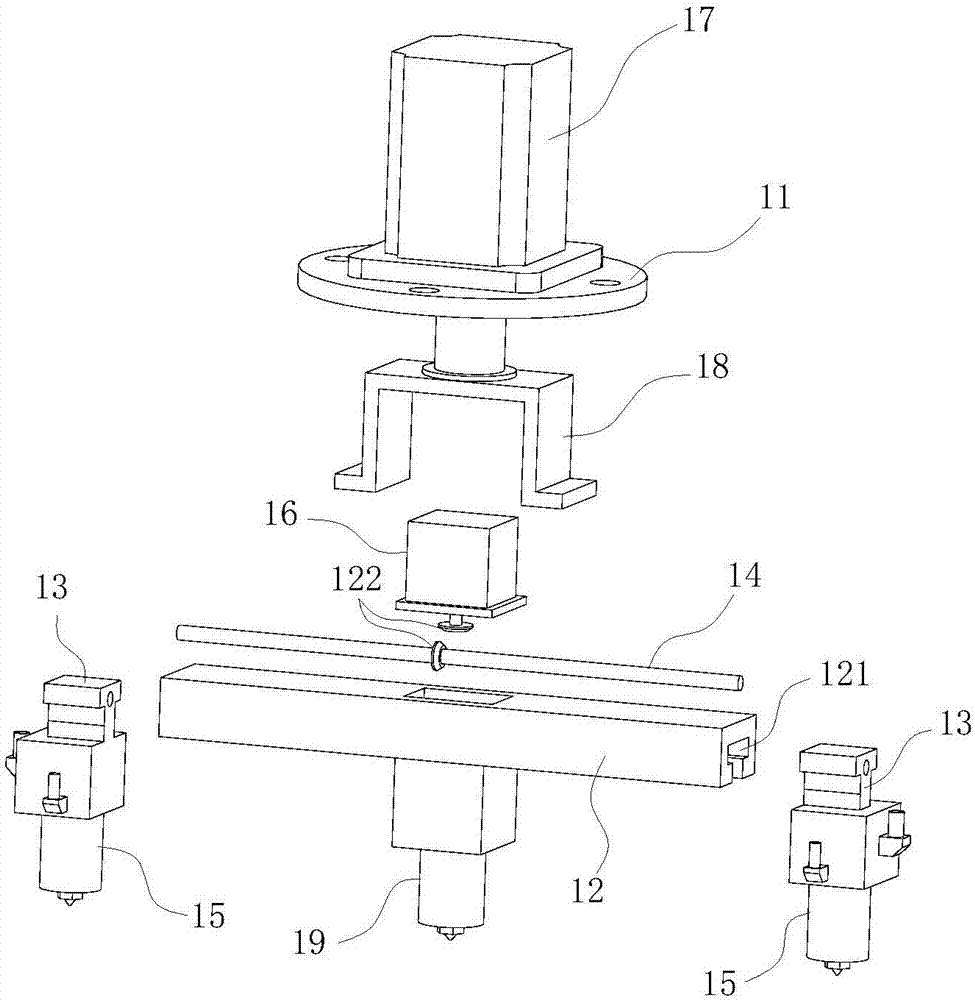
[0021] Such as figure 2 , 3 As shown, a rotary nozzle assembly 10, the rotary nozzle assembly 10 includes a connecting part 11 and a rotary part 12, the connecting part 11 is used to connect the nozzle 15 drive mechanism of the rotary nozzle assembly of the 3D printer, the rotary part 12 Rotate along the vertical axis and be arranged on the connecting part 11. At least two sliders 13 are arranged on the turning part 12, and each slider 13 is along the radial direction of a circular area with the turning center of the turning part 12 as the center. Slidingly arranged on the rotary part 12, and each slider 13 is set with the center of rotation of the rotary part 12 as a symmetrical point for synchronous and symmetrical movement; each of the sliders 13 is respectively equipped with a shower head 15, and the position of each shower head 15 is about The turning center of the turning part 12 is symmetrically arranged.

[0022] Preferably, a two-way screw rod 14 is arranged on the...

Embodiment 3

[0024] Such as Figure 4 As shown, in this embodiment, a double-link slider 13 mechanism is used to realize the synchronous movement of the two sliders 1313, including a linear motor 111, the main shaft 112 of the linear motor 111 is hinged to the two connecting rods 113, and the other ends of the two connecting rods 113 are respectively It is hinged with two sliders 1313 to convert the vertical motion of the main shaft 112 of the linear motor 111 into the horizontal motion of the slider 1313 .


PUM


Abstract

The invention belongs to the technical field of 3D printing, and particularly relates to a revolution sprayer assembly for a 3D printer. The revolution sprayer assembly comprises a connection part and a revolution part, the connection part is used for connecting a sprayer driving mechanism of the 3D printer, and the revolution part is rotatably arranged on the connection part along a vertical axis; at least two sliding blocks are arranged on the revolution part, each sliding block is arranged on the revolution part in a sliding mode in the direction of a radial line of a circular area that a revolution centre of the revolution part serves as a centre of a circle, and each sliding block is symmetrically and movably arranged around a symmetry point of the revolution centre of the revolution part in synchronism; and a sprayer is installed on each sliding block, and the position of each sliding block is arranged of the revolution centre of the revolution part in a centre symmetrical mode. The revolution sprayer assembly for the 3D printer comprises at least two sprayers moving symmetrically in synchronism, during printing, symmetrical structures on a model can be printed in synchronism, the printing time of the model is greatly shortened, and meanwhile, the process of programming is effectively simplified.

Description

technical field [0001] The invention belongs to the technical field of 3D printing, and in particular relates to a rotary nozzle assembly of a 3D printer. Background technique [0002] 3D printer, also known as three-dimensional printer (3DP), is a cumulative manufacturing technology, that is, a machine of rapid prototyping technology. It is based on a digital model file and uses special wax, powdered metal or plastic to bond materials, which create three-dimensional objects by printing layers of adhesive materials. At this stage 3D printers are used to manufacture products. The technology of constructing objects by printing layer by layer. The principle of a 3D printer is to put data and raw materials into the 3D printer, and the machine will build the product layer by layer according to the program. The 3D printing model in the prior art sometimes contains some symmetrical elements, and even the whole model is a symmetrical structure. When printing this kind of three-di...

Claims


Application Information

Patent Timeline
Patent Type & Authority Applications(China)
IPC IPC(8): B29C64/209B33Y30/00
CPCB33Y30/00
Inventor 牛莉张新建王甫段贤勇岳宏梅
Owner ANHUI TECHN COLLEGE OF MECHANICAL & ELECTRICAL ENG
Why Eureka
Try Eureka