
Dry gas holder piston steel concrete composite box girder

A dry gas tank and concrete technology, applied in the field of piston ring beam, can solve the problems of instability of piston fence, low operating pressure and high height of stiffener of piston box beam, and achieve the effect of fast, accurate and convenient position limitation

Pending Publication Date: 2017-07-21
HUATIAN NANJING ENG & TECH CORP MCC
View PDF6 Cites 0 Cited by
  • Summary
  • Abstract
  • Description
  • Claims
  • Application Information

AI Technical Summary

Problems solved by technology

[0004] In the design concepts of single-stage rubber membrane sealed gas cabinets and two-stage rubber membrane sealed gas cabinets, the concrete in the piston box girder is an important part of the force of the piston box girder. In the structure of the gas cabinet, the most complicated non- Piston box girder is none other than, and the good mechanical performance of concrete can improve the stress environment of piston box girder, but in actual engineering, owners often require the operating pressure of the gas tank to be lower, or require more movable counterweights, so As a result, the concrete pouring height in the piston ring beam is low, which makes it difficult to meet the structural force requirements. There have been several domestic cases where the entire piston ring beam was damaged due to insufficient concrete height, which in turn caused the overall instability of the entire piston fence, resulting in collapse. cause very serious accidents; on the other hand, the piston box girder is also used as a walkway, and when designing the piston box girder, a large number of stiffeners are often set inside the piston box girder due to the force requirements. When the gas tank pressure is high, the concrete pouring inside the piston box girder is full, and the use function of the piston box girder walkway is fully satisfied; when the gas tank pressure is low, the concrete pouring height is If it is lower, the height of the stiffeners of the piston box girder will be higher. At this time, the stiffeners will be higher than the concrete surface, which will cause great obstacles to the walkway function of the piston box girder and seriously affect the appearance

Method used


Image

  • Dry gas holder piston steel concrete composite box girder
  • Dry gas holder piston steel concrete composite box girder
  • Dry gas holder piston steel concrete composite box girder

Examples


Embodiment 1

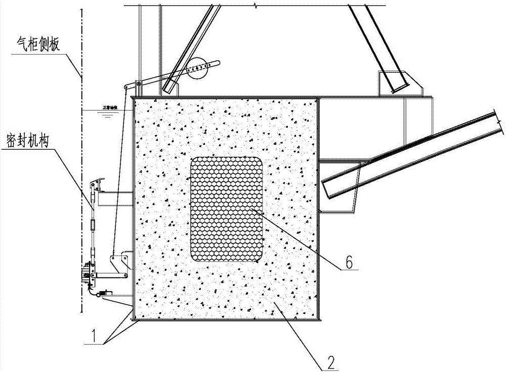
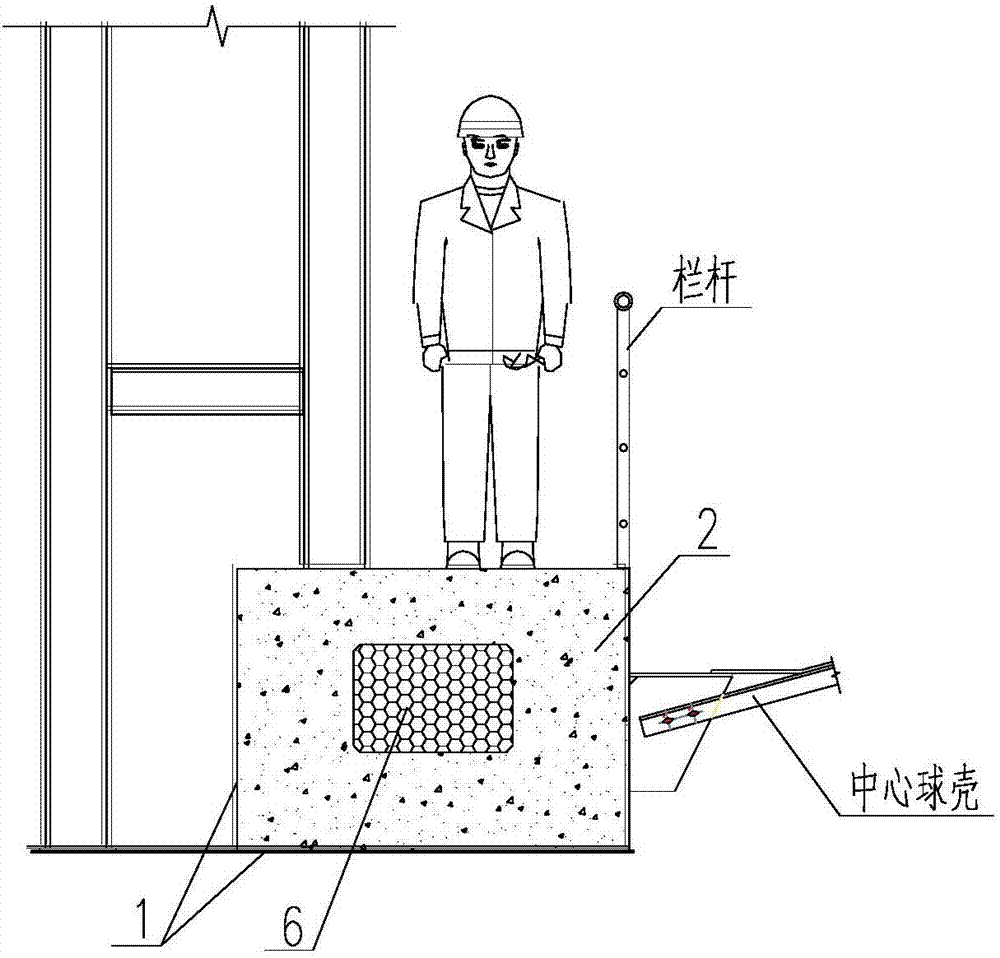
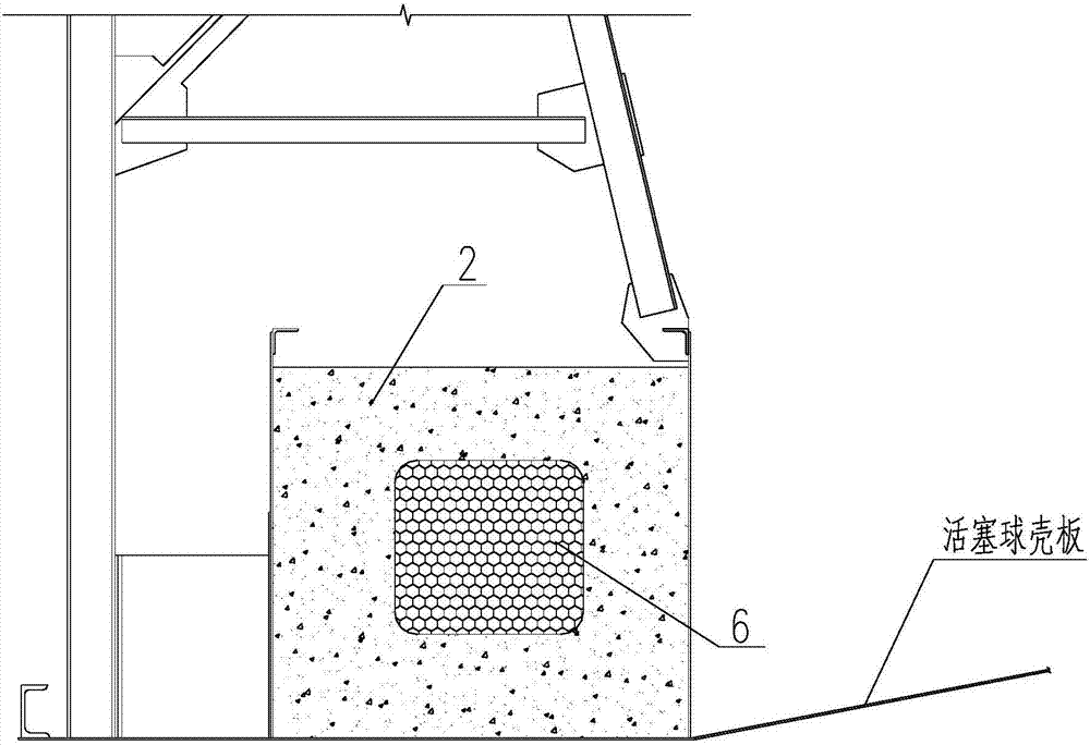
[0028] Such as Figure 1-6 As shown, a dry-type gas tank piston steel-concrete composite box girder of the present invention includes a box girder shell 1 with an open upper end and a box girder concrete 2; the inside of the box girder shell 1 is along the length direction of the box girder shell A light material 6 is extended, and the box girder concrete 2 is filled between the box girder shell 1 and the light material 6. It is characterized in that the light material 6 is limited by a positioning mechanism at a preset set location.

[0029] In the implementation process, the lightweight material should be set at the preset position in the box girder shell, and then concrete should be filled between the box girder shell and the lightweight material, and a positioning mechanism should be set to set the lightweight material at the expected position On the one hand, it is more accurate and convenient to define the position, and it can directly fill the uncured box girder concre...

Embodiment 2

[0030] Embodiment 2, on the basis of the above-mentioned embodiments, the positioning mechanism includes several lightweight material erecting ribs 7 arranged inside the box girder concrete 2 along the direction in which the lightweight material 6 extends; the lightweight material erecting One end of the rib 7 fixes the lightweight material 6 , and the other end extends to the bottom plate of the box girder shell 1 .

[0031] The light material is limited by erecting ribs. The lower end of the erecting rib abuts against the floor of the box girder shell, and the upper part surrounds the circumference of the longitudinal section of the light material, so that the position of the light material can be stably set, and the It can be included to a certain extent for lightweight materials and provide a certain strength.

Embodiment 3

[0032] Embodiment 3, on the basis of the above embodiments, the cross-section of the lightweight material 6 is a rectangle with four sides and the four sides of the ring beam cross-section;

[0033] The inside of the box girder concrete 2 is provided with light material erecting ribs 7 with a rectangular cross-section along the circumference of the light material 6, and the lightweight material erecting ribs 7 include a number of light material transverse bars parallel to the longitudinal section of the box girder. Erecting ribs 71, several vertical erecting ribs 72 of lightweight materials perpendicular to the longitudinal section of the box girder.

[0034] The setting of the vertical ribs of the light material not only supports the light material during the installation process, but also increases the strength to resist the shearing force.

[0035] Preferably, the number and position of the longitudinal ribs 72 are determined by the size of the cavity, and the size and spac...


PUM

PropertyMeasurementUnit
Thicknessaaaaaaaaaa

Abstract

The invention discloses a dry gas holder piston steel concrete composite box girder. The dry gas holder piston steel concrete composite box girder comprises an open box girder shell, box girder concrete, a box girder stirrup, a box girder longitudinal reinforcement, a fluke, a lightweight material, a lightweight material bearing rod, a lightweight material block, and a piston box girder stiffening rib. The fluke is welded in the inside of the open box girder housing, the box girder stirrup and the box girder longitudinal reinforcement are located on the outside of the box girder, the lightweight material is arranged in the middle of the piston box girder, the bearing rod is arranged on the outside of the lightweight material, A certain amount of lightweight material blocks are arranged between the bearing rod and the lightweight material; the piston box girder stiffening rib is located on the inside of the piston box girder, and welded on the inside of the open box girder shell; and the box girder concrete is filled in the inner part of the open box girder shell. The dry gas holder piston steel concrete composite box girder solves the problems that the mechanical behavior of the structure and the piston box girder stiffening rib protruding and unable to form walkway caused by low pressure and the piston box girder concrete pouring insufficient are decreased, the investment is low, the construction time is short and the economic benefit is considerable.

Description

technical field [0001] The invention relates to a piston ring beam, in particular to a dry-type gas tank piston steel concrete composite box beam. Background technique [0002] After decades of development, dry-type gas holders have been widely used in metallurgy, petrochemical and other industries. At present, the commonly used dry-type gas holders are regular polygon thin oil-sealed gas holders, two-stage rubber membrane-sealed gas holders, Single-stage rubber-membrane-sealed gas cabinets, new-type cylindrical gas cabinets and kolon-type gas cabinets, except for the regular polygonal thin oil-sealed gas cabinets without piston ring beams, the pistons of other cabinet types have piston ring beams. With the increase in the number of gas tanks put into production, some problems in use are gradually reflected, and one of the more prominent ones is the problem of the concrete height of the piston box girder. [0003] In the design concept of the new cylindrical gas tank and th...

Claims


Application Information

Patent Timeline
IPC IPC(8): F17B1/24F17B1/02
CPCF17B1/02F17B1/24
Inventor 陈祥勇杜宣刚王东
Owner HUATIAN NANJING ENG & TECH CORP MCC
Learn More