Boiler flue gas treatment device

A technology for treating device and boiler flue gas, which is applied in the fields of dispersed particle filtration, lighting and heating equipment, dispersed particle separation, etc. Frequency, extended use time, quick and convenient maintenance

Inactive Publication Date: 2017-07-21
HEFEI ZHIHUI LONGTUTENG INTPROP CO LTD
View PDF0 Cites 12 Cited by
  • Summary
  • Abstract
  • Description
  • Claims
  • Application Information

AI Technical Summary

Problems solved by technology

Therefore, the discharge of boiler tail gas is a problem that people have been paying attention to, and its discharge is not filtered, which will inevitably cause damage to nature.
[0003] Existing dry tail gas treatment devices generally pass the tail gas into the box containing the adsorbent material, absorb harmful substances and then discharge it, but there are still the following shortcomings: due to the limitation of the characteristics of the adsorbent material itself, after a period of use It needs to be replaced, and the existing adsorption material is inconvenient to replace, which reduces the maintenance efficiency; dust is easy to scale in the pipeline, clogs the pipeline, and is difficult to clean; the filter cloth used for dust filtration becomes poor after a period of use, resulting in the need Frequent replacement will not only affect the normal operation of the equipment, but also lead to increased maintenance costs

Method used


Image

  • Boiler flue gas treatment device
  • Boiler flue gas treatment device

Examples


Embodiment Construction

[0016] The following will clearly and completely describe the technical solutions in the embodiments of the present invention with reference to the accompanying drawings in the embodiments of the present invention. Obviously, the described embodiments are only some, not all, embodiments of the present invention. Based on the embodiments of the present invention, all other embodiments obtained by persons of ordinary skill in the art without making creative efforts belong to the protection scope of the present invention.

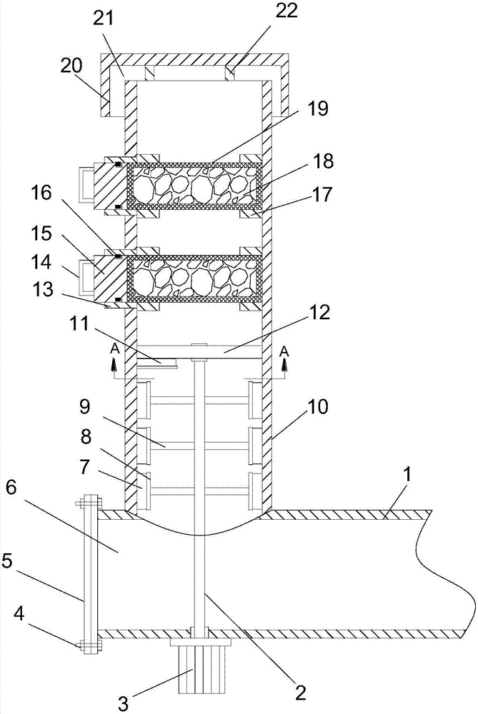
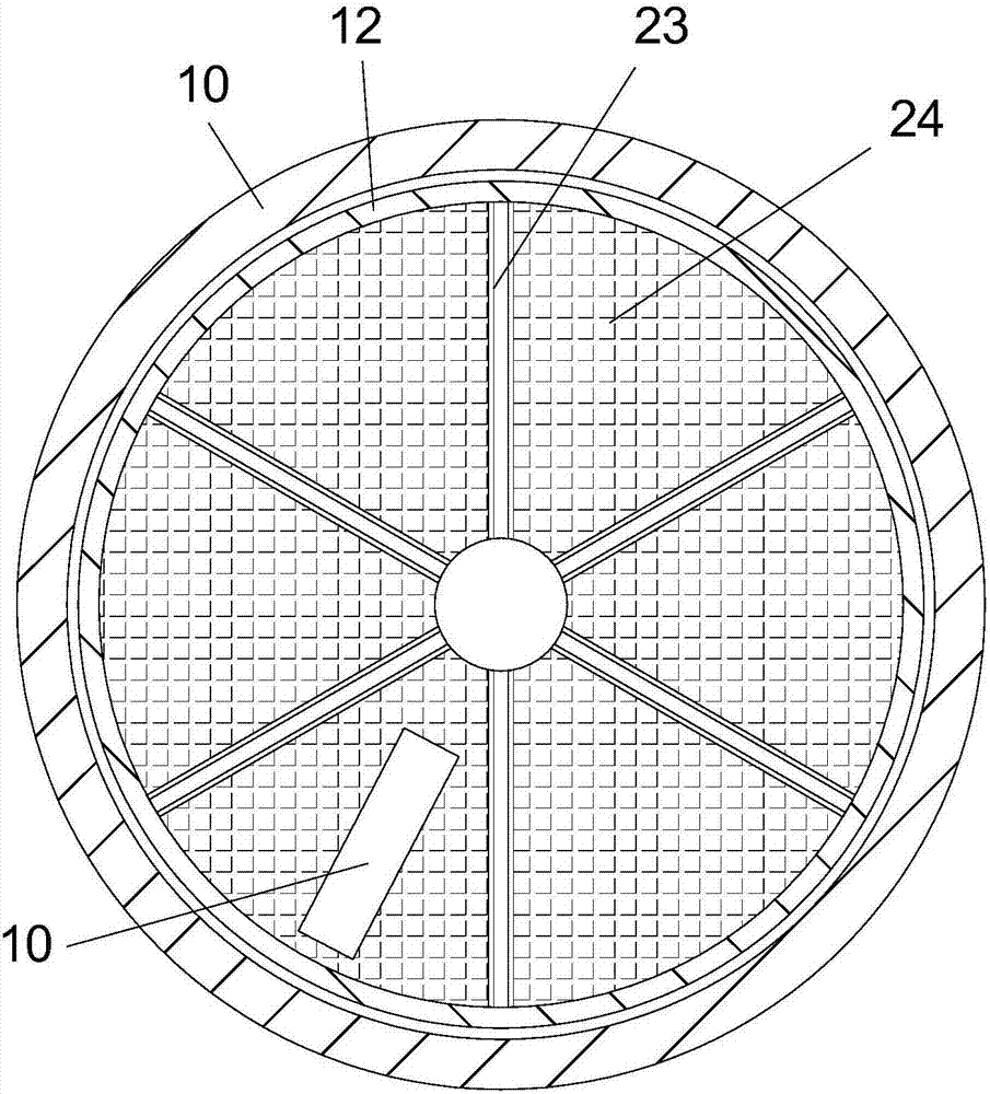
[0017] see Figure 1-2 , a boiler flue gas treatment device, comprising an air intake pipe 1 and an exhaust pipe 10, the air intake pipe 1 is arranged horizontally and its right end communicates with the boiler smoke exhaust port, the left end of the air intake pipe 1 is provided with an ash discharge port 6, The ash outlet 6 is installed with a plug 4 through the bolt assembly 5; the exhaust pipe 10 is vertically arranged and its lower end is welded to the up...


PUM


Abstract

The invention discloses a boiler flue gas treatment device. The boiler flue gas treatment device comprises a gas inlet pipe and a gas outlet pipe and is characterized in that the gas inlet pipe is horizontally arranged, and the right end of the gas inlet pipe communicates with a boiler smoke outlet; an ash discharging outlet is formed in the left end of the gas inlet pipe and is further provided with a plug through a bolt assembly; the gas outlet pipe is vertically arranged, and the lower end of the gas outlet pipe communicates with the upper end of the gas inlet pipe in a welding mode; a rotating shaft is vertically arranged on the lower portion of the inside of the gas outlet pipe, and an annular framework is arranged outside the upper end of the rotating shaft; the outer wall of the framework and the inside of the gas outlet pipe achieve motion sealing, and the inner wall of the framework is fixedly connected with the rotating shaft through a plurality of reinforcing ribs; and a filter cloth is arranged in a space formed between the reinforcing ribs and the framework. The novel structure is reasonable in design, using is convenient, dust in boiler tail gas can be removed, hazardous substances can be adsorbed, and the environment is protected; and the phenomenon that soot scaling happens to block the gas outlet pipe is avoided, the replacing frequency of the filter cloth is reduced, the replacing efficiency of an adsorbing material is improved, later maintenance by workers is facilitated, and the labor intensity is lowered.

Description

technical field [0001] The invention relates to the field of tail gas treatment, in particular to a boiler flue gas treatment device. Background technique [0002] At present, various boilers are not only widely used in industry, but also more and more widely used in people's daily life. The main emissions from boiler combustion are sulfur dioxide and dust, among which sulfur dioxide is one of the main pollutants that cause acid rain. . Therefore, the discharge of boiler tail gas is a problem that people have been paying close attention to, and its discharge cannot be filtered clean, which will inevitably cause damage to nature. [0003] Existing dry tail gas treatment devices generally pass the tail gas into the box containing the adsorption material, absorb harmful substances and then discharge it, but there are still the following shortcomings: due to the limitation of the characteristics of the adsorption material itself, after a period of use It needs to be replaced, ...

Claims


Application Information

Patent Timeline
Patent Type & Authority Applications(China)
IPC IPC(8): F23J15/02B01D46/10B01D53/04
CPCF23J15/025B01D46/10B01D53/0407F23J15/02F23J2217/10
Inventor 不公告发明人
Owner HEFEI ZHIHUI LONGTUTENG INTPROP CO LTD
Why Eureka
Try Eureka