
Measuring method, controller and control system of conductor-to-ground insulation resistance

A technology of insulation resistance and insulation resistance to ground, applied in the field of electronics, can solve the problems of inability to effectively control the defect rate of glass substrates and accurately detect insulation resistance, etc., to improve the yield rate and product quality, low cost and high measurement accuracy. Effect

Active Publication Date: 2019-10-08
ZHENGZHOU XUFEI OPTOELECTRONICS TECH +1
View PDF11 Cites 0 Cited by
  • Summary
  • Abstract
  • Description
  • Claims
  • Application Information

AI Technical Summary

Problems solved by technology

[0003] The purpose of this disclosure is to provide a measurement of conductor-to-ground insulation resistance in order to solve the problem in the prior art that the defect rate in the glass substrate manufacturing process cannot be effectively controlled due to the inability to quickly and accurately detect the ground-to-ground insulation resistance of the platinum body Method, controller and control system

Method used


Image

  • Measuring method, controller and control system of conductor-to-ground insulation resistance
  • Measuring method, controller and control system of conductor-to-ground insulation resistance
  • Measuring method, controller and control system of conductor-to-ground insulation resistance

Examples


Embodiment Construction

[0054] Specific embodiments of the present disclosure will be described in detail below in conjunction with the accompanying drawings. It should be understood that the specific embodiments described here are only used to illustrate and explain the present disclosure, and are not intended to limit the present disclosure.

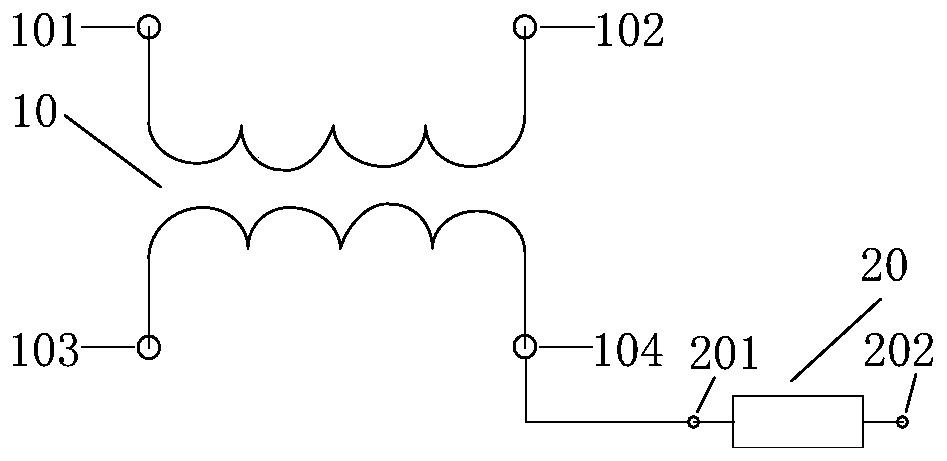
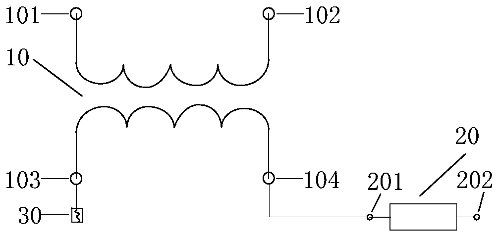
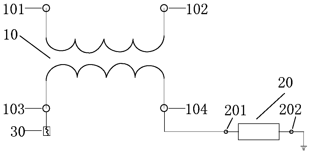
[0055] Figure 1A It is a structural schematic diagram of a measuring circuit for conductor-to-ground insulation resistance shown according to an exemplary embodiment. Such as Figure 1A As shown, the measuring circuit for the conductor-to-ground insulation resistance may include: a transformer 10 and a test resistor 20 .

[0056] In the present disclosure, the primary-side terminal of the transformer 10 can be used to connect to a power supply, that is, the primary-side first input terminal 101 and the primary-side second input terminal 102 of the transformer 10 can be used to connect to a power supply, wherein the The transformer 10 may be, for example, ...


PUM


Abstract

The present disclosure relates to a measurement method of the insulation resistance to ground of a conductor, a controller and a control system. The method includes the following steps that: first current flowing through a test resistor when a first output terminal is connected with the conductor and the second end of the test resistor is grounded is obtained; the secondary side output open-circuit voltage of a transformer, second current flowing through the test resistor when the first output terminal is in butt joint with the second end of the test resistor, and a first voltage between the first output terminal and the second end of the test resistor when the first output terminal is in butt joint with the second end of the test resistor are obtained; and the insulation resistance to ground of the conductor is determined according to the secondary side output open-circuit voltage, the first current, the first voltage and the second current. Therefore, the insulation resistance to ground of the conductor can be quickly and accurately obtained. The measurement circuit of the insulation resistance to ground of the conductor is simple, the components of the measurement circuit are low in cost, and the measurement accuracy of the measurement circuit is high. With the measurement method adopted, the defect rate of a glass substrate manufacturing process can be effectively reduced, and the yield and quality of products can be improved.

Description

technical field [0001] The present disclosure relates to the field of electronic technology, in particular, to a method for measuring insulation resistance of a conductor to ground, a controller and a control system. Background technique [0002] In the manufacturing process of the glass substrate, when the insulation effect of the platinum channel to the ground is not good, the ion state of the molten glass liquid in the platinum channel will change, so that the glass substrate is prone to defects. Therefore, quickly and accurately detecting the insulation resistance of the platinum body to ground has an important impact on the defect rate control in the glass substrate manufacturing process. Contents of the invention [0003] The purpose of this disclosure is to provide a measurement of conductor-to-ground insulation resistance in order to solve the problem that the defect rate in the glass substrate manufacturing process cannot be effectively controlled due to the inabi...

Claims


Application Information

Patent Timeline
Patent Type & Authority Patents(China)
IPC IPC(8): G01R27/20G01R27/08
Inventor 吴军苏记华王展吴宏斌沈先良严雷贾礼礼
Owner ZHENGZHOU XUFEI OPTOELECTRONICS TECH
Learn More